 |
|||
|
|
|||
| ||||||||||
|
|  Lubrication.- An adequa te and self-contalneci lubricating system of the force feed type
shall be provided for the main bearings, crankpin bearings, wrist-pin bearings, gears, pinion and
similar items. Consideration will be given to splash feed systems or a combination of splash and force
feed systems, The crankpit shall be suitably housed to form a reservoir for the lubricating oil, Splash
guards shall be fitted to prevent oil from the crankcase entering the air cylinders. The crankpit
reservoir shall be provided with suitable fittings for filling and draining of the lubricating oil. A suitable
oil-level gage, marked to show the high, low and normal oil levels, shall be fitted. Gage glasses, if
used, shall be renewable without draining the Oil from the reservior. Oil shall be drawn from the
reservoir by one or more pumps, positively driven from the compressor crankshaft. The arrange ment
of the reservior and pump connection shall be such that oil will not be lost from th reservoir, nor the
oil pu mp lose suction due to roll or pitch of the vessel. The oil shall be properly strained and cooled
before being delivered to the parts to be lubricated, Strainer (if provided) shall be fitted on the discharge
side of the lubricating. oil pump. Satisfactory means of cooling the oil shall be provided. Oil coolers,
if provided, shall conform to type A of Specif ication MIL-C-15730. Coolers shall be class 2 unless
otherwise specified (see 6. 1). The coolant side shall be given a hydrostatic test of 225 p. s. i. g. unless
otherwi se specified (see 6. 1). Suitable means shall be provided for regulating the pressure of the lubri-
in accordance with Specification MIL- L-17331.
3.3.12 Bedplate. - The bedplate shall be continuous under the compressor and its driving unit.
It shall be machined to receive the Intermediate frames or housing, or may be integral therwith. All
top and bottom bearing surfaces shall be machine finished. Bedplates shall be sufficiently rigid to per-
mit handling, shipment, and installation of the units onboard ship, without disturbing the alignment of
the assembled units, and such that the normal distortion, weaving or vibration of the supporting struc-
tures onboard ships cannot cause misalignment of components
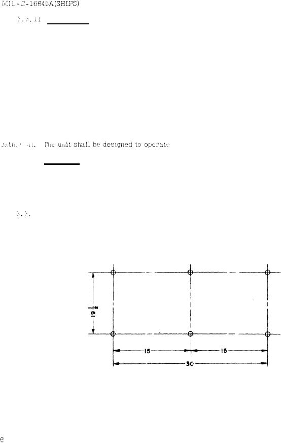
12.1 The basis of size 10 compressors shall have six 3/4 inch holes for 1 /8-inch foundation:
bolts, arranged as shown on figure 1.
Figure 1.- Size 10 compressors
|
|
Privacy Statement - Press Release - Copyright Information. - Contact Us |
