 |
|||
|
Page Title:
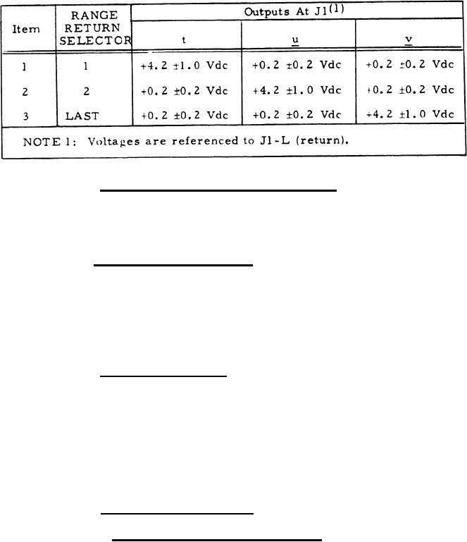
Table II. Range Return Selection Responses |
|
||
| ||||||||||
|
|  MIL-C-50734(MU)
8 August 1973
TABLE II
RANGE RETURN SELECTION RESPONSES
3 . 3 . 1 . 3 L A S E R M O D E C O N T R O L s w i t c h . With the LASER
MODE CONTROL switch set to each position in turn, the circuit condi-
tions and voltages at the designated terminals shall be as specified in
t a b l e III.
3.3.1.4 Dimmer (DMR) switch. Depressing the DMR switch shall
cause all indicators other than the RANGE (METERS) and RETURNS, to
change either from bright to dim or from dim to bright. When the indi-
cators are bright, the voltages at J1-AA and J1-M shall be +13.5 1.5 Vdc
and +15.0 1.5 Vdc, respectively. When the indicators are dim, the
voltages at J1-AA and J1-M shall be +8.5 2.0 Vdc, and +10.0 2.0 Vdc,
respectively.
3.3.1.5 Test switch (TSW). Depressing the TSW switch shall
cause:
a. All indicators to light.
b. Each RANGE (METERS) and RETURNS readout to display
the number 8, and
c. The voltage at J1-N to be +0.8 0.4 Vdc.
3 . 3 . 1 . 6 Indicator
illumination
3 . 3 . 1 . 6 . 1 R A N G E R E T U R N S E L E C T O R indicators. The 1, 2,
and LAST indicators shall light when depressed. Only the indicator
depressed last shall be lighted.
5
|
|
Privacy Statement - Press Release - Copyright Information. - Contact Us |