 |
|||
|
Page Title:
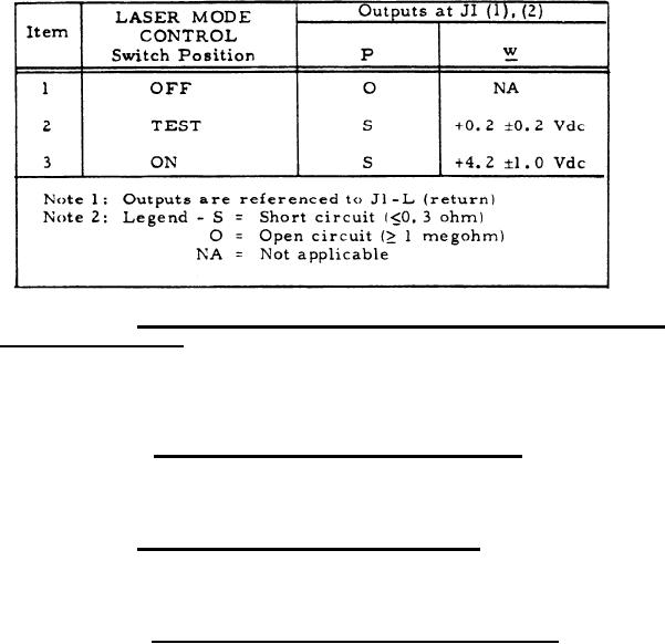
Table III. Laser Mode Control Switching Responses |
|
||
| ||||||||||
|
|  MIL-C-50734(MU)
8 August 1973
TABLE III
LASER MODE CONTROL SWITCHING RESPONSES
3.3.1.6 Battery-low/drain (BAT-LOW/DR) and malfunction
(MALF) indicators. With the logical zero type-A signal (item 3.1) of
table I applied to J1-p, the MALF indicator shall light. With the logical
zero type-B signal (item 3.2) of table I applied to J1-S and to J1-CC, the
BAT-LOW and BAT-DR indicators, respectively, shall light.
3.3.1.6.3 LASER MODE CONTROL indicators. With the
LASER MODE CONTROL switch set to ON or TEST, the ON or TEST
indicator, respectivety shall light.
3.3.1.7 RETURNS readout selection logic. With the digital type-A
signal of table I applied as specified in table IV, the readout number on the
RETURNS display shall be as specified in table IV.
3.3.1.8.5 RANGE (METERS) readout selection logic. With the
digital type-A signal (item 3.1) of table 1 applied as specified in table V,
each of the four display positions of the RANGE (METERS) readout shall
indicate as specified in table V.
6
|
|
Privacy Statement - Press Release - Copyright Information. - Contact Us |
