 |
|||
|
Page Title:
Figure 1. Converter Drive Signal Waveforms |
|
||
| ||||||||||
|
|  MIL-C-50740(MU)
8 August 1973
3.3.1.3 Battery drain light drive. With the power sources (item 2)
of Table I applied and with the input voltage at P1-15 set to +24.O 2.O Vdc, the
voltage at P1-1 shall be 15.0 1.O Vdc. With the voltage at P1-15
decreased to +16.5 0.5 Vdc, the voltage at P1-1 shall be + 1.0 O.7 Vdc.
3.3.1.4 Battery low light drive. With the power sources [item 2)
of table I applied, and with +25.0 0.5 Vdc then +21.0 1.0 Vdc applied
to pin P1-6, the output at pin P1-11 shall be +15.0 1.0 Vdc and
+0.4 0.4 Vdc respectively.
3.3.1.5 MALF 1 signal. With the power sources (item 2) of
table I applied, and with +24.0 0.2 Vdc applied to P1-6, the output at
P1-14 shall be +0.2 0.2 Vdc. With P1-20 connected to P1-6, the output
at P1-14 shall be +5.0 0.3 Vdc.
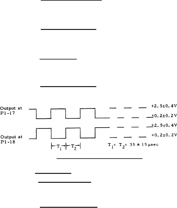
3.3.1.6 Converter drive signal. With the power sources (item 2)
of table I applied, the output voltage at P1-17 and P1-18 shall be as shown
in figure 1.
Figure 1. Converter Drive Signal Waveforms
3.3.2 Environmental
3.3.2.1 Storage temperature. The assembly shall meet the require-
ments of 3. 3.1 at ambient temperature after exposure to and thermal
stabilizatio at -80F and +160F.
3.3.2.2 Operating temperatures. The assembly shall meet the
requirements of 3.3.1 while exposed to and thermally stabilized at -40F
and +125F, subsequent to which the requirements of 3. 3.1 shall be met at
ambient temperature.
5
|
|
Privacy Statement - Press Release - Copyright Information. - Contact Us |
