 |
|||
|
|
|||
| ||||||||||
|
|  MIL-C-50743(MU)
8 August 1973
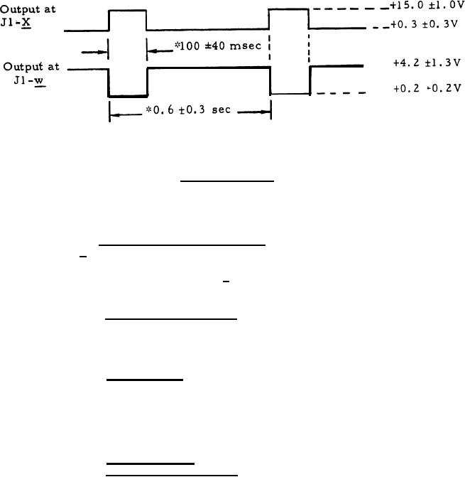
*At the temperatures extremes of 3.3.2.2 the pulse width shall be
100 60 msec, and the pulse spacing shall be 0.6 O.5 sec.
Figure 6, RANGE LIGHT Signal Waveform
3. 3.1.9 PFN voltage programming. With the PFN voltage at J3-A
set to +1200 + 15V, changing the load between J2-b and J2-c from 100 kilohms
(item 1,2, table I) to 32.4 kilohms (item 1.3, table I) shall cause the PFN
voltage at J3-A to increase to +1 345 + 40V.
3.3.1.10 PFN voltage sensing. With the PFN voltage at J3-A set
to +1200 15V, the current through a microammeter connected between
J5-t and J5-e shall be 75 3 microampe res.
3.3.1.11 FIRE signal. With the PFN voltage at J3-A set to +1200
200V, with the input signals (items 3.1 and 3.3 of table I) and input pin
connection conditions established for the input pins as listed in table V
for each item listed therein, and with the table V items conditions
established in the order item 1 through item 6, the corresponding ordered
outputs at J2-e shall be as listed therein.
3.3.1.12 Malfunction 4 signal.
a.
With the PFN voltage at J3-A set to +1200 200V, with the input
signal (item 3.3 of table I) conditions established for the input
pins as listed in table VI for each item listed therein, and with
the table VI items conditions established in the order item 1
through item 6, the corresponding ordered outputs at J1-d
shall be as listed therein.
12
|
|
Privacy Statement - Press Release - Copyright Information. - Contact Us |
