 |
|||
|
|
|||
| ||||||||||
|
|  MIL-c-62202B(AR)
3.3.3 Readout selection logic. With the table II items input conditions
established in the item number order, the corresponding ordered readout display
conditions shall be as specified therein. (See 4.6.1.3)
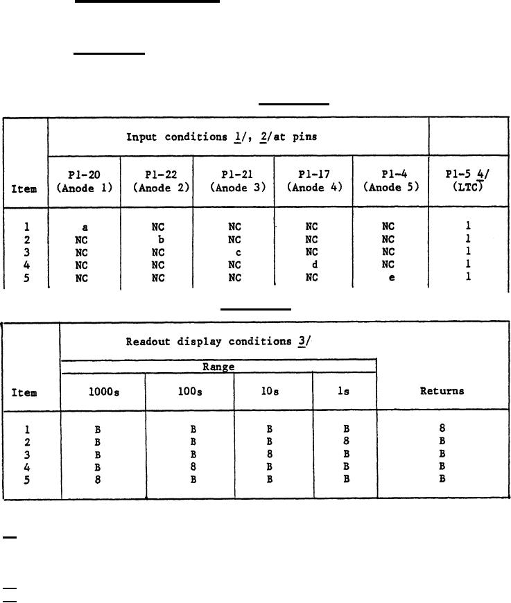
3.3.4 Anode logic. With the table III items input conditions estab-
lished in the item number order, the corresponding ordered readout display
conditions shall be as specified therein. (See 4.6.1.4)
TABLE III. Anode logic.
TABLE III. Anode logic. - Continued
1/ Input signal condition voltages are referenced to pin P1-7.
2/ Input signal condition legend:
a. Signals a, b, c, d and e are node input signals, item 3.1 of table I.
b. NC = no connection
c. O = logical zero digital type-a signal, item 3.1 of table 1.
3/ Readout display condtion legend: B = blank - not illuminated
4/ Input terminal legend: LTC is Lamp test control.
9
|
|
Privacy Statement - Press Release - Copyright Information. - Contact Us |
