 |
|||
|
Page Title:
Figure 9. Format of Input Word to Digital Input Multiplexer from Universal Keyset Logic |
|
||
| ||||||||||
|
|  MIL-D-81347C(AS)
(6) Selectively set or reset each of four flip-flops. Each flip-
flop controls the illumination of a colored background message on a Matrix Readout switch not con-
trolled by (5). An output from each of the flip-flops shall be supplied to the Universal Keyset.
(7) Reset the storage registers for PRO's 7-9.
(8) Enable one of the test loops contained in the UKL.
Each UKL shall be self initializing; i.e. , when power is applied
to a UKL, no spurious data shall be transmitted to the DIM and the UKL shall be ready for normal
operation.
Test Loops - Test Loops shall be designed into each UKL. The
3.5.1.4.4.4
test loops shall permit the computer program to exercise a UKL and monitor the performance for
possible logic malfunctions. The test loops shall be comprehensive: i. e. , the test loops shall exercise
every logic element in a UKL in all of its functions insofar as possible. The test loop shall be utilized
for in-flight performance monitoring (IFPM) and diagnostic programs.
Interface Requirements - Refer to the functional flow diagram
3.5.1.4.4.5
for the UKL Subunit, Figure 12.
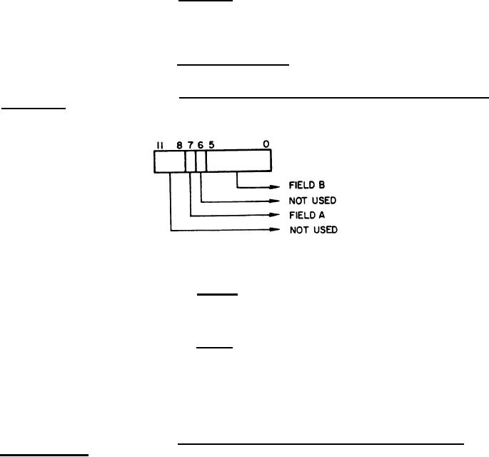
Format of Input Word to Digital Input Multiplexer from Universal
3.5.1.4.4.5.1
Keyset Logic - Refer to Figure 9.
Figure 9. Format of Input Word to Digital Input Multiplexer from Universal Keyset Logic
(1) Field A - Identifies test loop operation data, i.e. , if bit 7
is a logical "l", the data contained in the remainder of the input word to the computer is not the result
of a switch depression on the Universal Keyset but is due to test loop operation of the UKL by the com-
puter program.
(2) Field B - Identifies the switch depressed or contains the
data resulting from test loop operation.
NOTE
Bits 0-5 and 7 of the input word to the DIM form
bits 0-5 and 7 of the input word from the DIM to
the computer.
3.5.1.4.4.5.2
Format of Output Word to Universal Keyset from the Digital
Output Multiplexer - Refer to Figure 10.
(1) Field A - Specifies which one of the following operations is to
be performed.
(a) Field C is a message combination selection code for the
Matrix Readout switches and shall be stored in the appropriate register.
39
|
|
Privacy Statement - Press Release - Copyright Information. - Contact Us |
