 |
|||
|
Page Title:
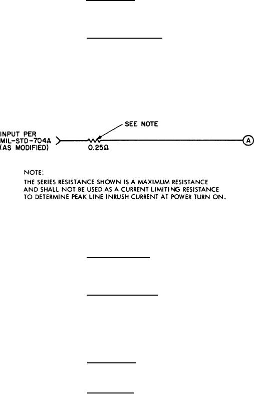
Figure 149. MDM Input Power Source |
|
||
| ||||||||||
|
|  MIL-D-81347C(AS)
Warmup Time - The time required for the MDM to warm up
3.5.4.4.4.3.3.2.14
prior to operation shall be kept to a minimum and shall not exceed 25 seconds for temperatures from
0 C to and including +55 C and shall not exceed 4.5 minutes for temperatures from less than 0 C to
and including -25 C.
Input Electrical Power - The MDM shall operate with power as
3.5.4.4.4.3.3.2.15
received at point A of Figure 149. The input to Figure 149 shall be as specified in MIL-STD-704A
except that curve 3 of Figure 3 shall be modified such that its lower limit shall not fall below 80 volts.
The MDM shall operate with three phase 400 HZ 115/200 volt (nominal) AC power. The total MDM
power shall be 305 35 watts during normal operation. The maximum power required by the MDM of
duration greater than 2 seconds but less than 60 seconds shall not be greater than 850 watts. Peak
line current at power turn-on shall not exceed 105 amperes/phase and shall be below 10 amperes two
milliseconds after power turn-on. No single phase power usage shall be allowed without the use of the
three-phase neutral power return.
Figure 149. MDM Input Power Source
Normal Conditions - Normal voltage conditions are defined as
3.5.4.4.4.3.3.2.15.1
those voltage conditions which fall within the area defined by the curves obtained at point A of Figure
149 when the input to Figure 149 consists of curves 2 and 3 (as modified) of Figure 3 of MIL-STD-704A.
The MDM shall perform as specified for all normal voltage conditions.
Abnormal Conditions - Abnormal voltage conditions are defined
3.5.4.4.4.3.3.2.15.2
as those voltage conditions which fall outside the area defined the area defined by curves obtained at point A of Figure
149 when the input to Figure 149 consists of curves 2 and 3 (as modified) in Figure 3 of MIL STD-704A
but remain within the area defined by the curves obtained at point A when the input to Figure 149 con-
sists of curves 1 and 4 in Figure 3 of MIL-STD-704A. The MDM may malfunction during abnormal
voltage conditions but shall automatically resume normal operation when the voltage conditions return
within normal limits. No damage to the equipment or destruction of data already stored shall occur
due to abnormal voltage conditions.
Loss of Power - No damage to the MDM or destruction of data
3.5.4.4.4.3.3.2.15.3
already stored shall occur due to accidental or deliberate disruption of all three phases of input power
regardless of the time in its operating cycle or the duration of interruption.
Power Factor - Power factor shall be defined as the ratio of
3.5.4.4.4.3.3.2.15.4
real power per phase to volt amperes per phase (product of RMS phase voltage and RMS phase cur-
rent). For a total real power of 305 35 watts, the MDM shall have a leading power factor on all
phases from 0.800 to 0.950.
264
|
|
Privacy Statement - Press Release - Copyright Information. - Contact Us |
