 |
|||
|
Page Title:
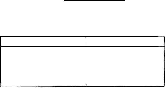
Table 1-2. Control Signals in Inter-Computer Channels |
|
||
| ||||||||||
|
|  MIL-D-81347C(AS)
(5) The External Function should be used to clear the External
Function Request at the peripheral equipment.
(6) Peripheral equipment samples the External function word.
(7) Computer drops the External Function line.
This sequencers repeated when the peripheral equipment is
ready to accept another External Function word.
If an External Function with force is to be sent, then steps (3),
(4), (6), and (7) would form the sequence as shown in Figure 1-6. Further External Function line.
Function with force can be found in 2.2.2.2.
Inter-Computer Communications - In the Computer any or all of
2.1.4.2
the input/output channels shall be cabling of being used for inter-computer communication. The con-
trol signals governing inter-computer communication are shown in Table 1-2.
TABLE 1-2. CONTROL SIGNALS IN INTER-COMPUTER CHANNELS
Input
output
Interrupt Enable
External Function Request
Interrupt
External Function
Input Data Request
Ready
Input Acknowledge
Resume
Note that the control signals in the input cable are the same for
inter- computer communications as for communication with peripheral equipment. In the output con-
trol line cable, Ready and Resume signals are used to control the inter-computer transfer of data.
Figure 1-2 illustrates the interface between two Computers.
Computer A is transmitting to Computer B.
330
|
|
Privacy Statement - Press Release - Copyright Information. - Contact Us |
