 |
|||
|
Page Title:
Figure 1. Battery Power Switching Waveforms |
|
||
| ||||||||||
|
|  MIL-E-50738(MU)
8 August 1973
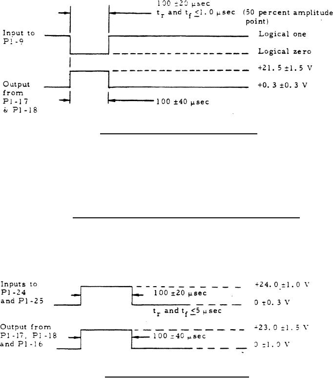
Figure 1. Battery Power Switching Waveforms
3.3.1.4 Batter power, voltage sense. With the power source of
table I applied to P1-22, P1-21, and P1-11, the output voltage at P1-10,
P1-8 and P1-15 shall be +12.0 1.5 Vdc, +24.0 1.5 Vdc
respectively. With the power source of table I applied to P1-14, the
output voltage at P1-15 shall be +11.5 1.5 Vdc.
3.3.1.5 Tank power, primary power, and Q-switch voltage. With
the loads (item 1.2 of table I) connected to P1-17 and P1-18, with the load
(item 1.1 of table I) connected tp P1-16, and with the signal source (item
3.2) of table I applied to P1-24 and P1-25, and output at P1-17, P1-18 and
P1-16 shall be as shown in figure 2.
Figure 2. Tank Power Switching Waveforms
5
|
|
Privacy Statement - Press Release - Copyright Information. - Contact Us |
