 |
|||
|
|
|||
| ||||||||||
|
|  MIL-E-63300A(AR)
APPENDIX
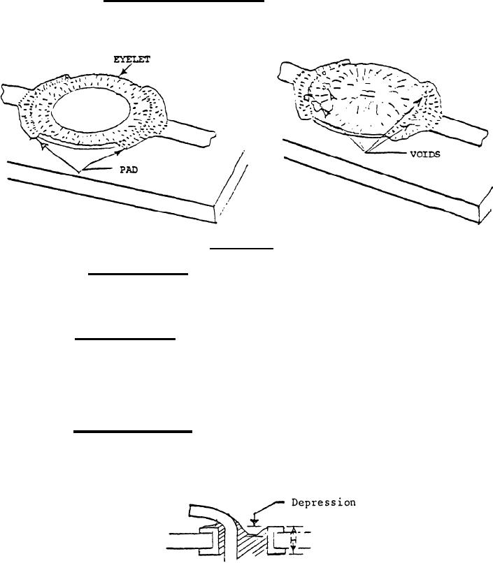
40.2.1.5 Eyelet connection voids. The total cumulative area of
all voids is less than 20% of the total interface between eyelet and
pad. Void(s) do not visibly expose base metal. The presence or
lack of solder in the eyelet hole is not basis for nonacceptability.
ACCEPTABLE
40.2.2 Maximum solder. A solder joint where it can be estab-
lished that the lead exists and solder does not overflow beyond the
confines of the connection area (the pad and tracks). Lead and pad
must be well wetted.
40.3 Lifting of pad. Lifted pads shall be controlled.
Quantity of boards with lifted pads shall be controlled by the
contractor as follows: Lifted pads exceeding 1/3 lifted to 0.40%
AQL. Lifted pads less than 1/3 lifted is 1.0% AQL. Damage must not
be in quadrant enclosing track. Damage not to break into plated
through hole. No damage to opposite hole.
40.4 Lead, solder side. Exposed end (except copper) are
visible at the end of the end. Lead is not closer than .015" to
adjoining conductive circuitry. Maximum solder is permissible.
Solder fillet is depressed, but the depression is less than 25% of
the board thickness.
45
|
|
Privacy Statement - Press Release - Copyright Information. - Contact Us |
