 |
|||
|
Page Title:
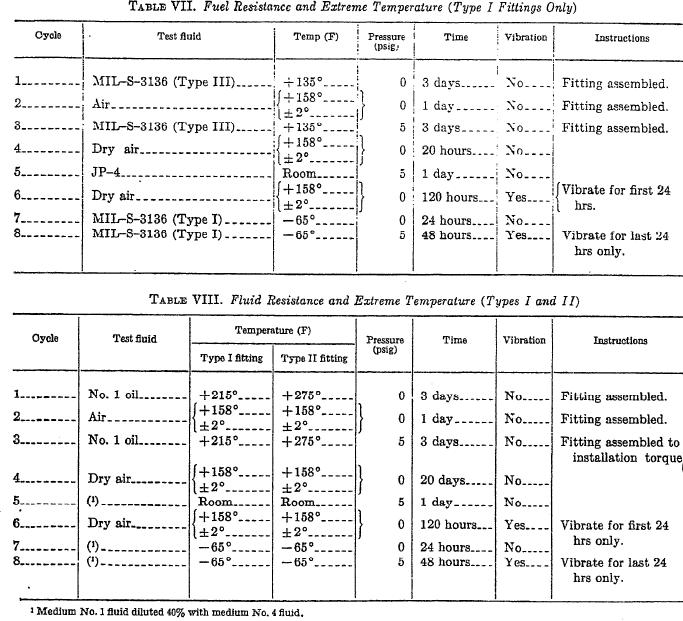
Table VII. Fuel Resistance and Extreme Temperature (Type I Fittings Only) |
|
||
| ||||||||||
|
|  MIL-F-5577B
vibration jig to accomplish this test. The sys-
shall be tested to the requirements of 3.10. Six
tem shall remain under pressure at ambient tem-
peratures for 30 days. Brown paper or talc
inserts shall be used for each test. Additional
fittings shall be used if required. Failure shall
shall be used for determination of fitting leak-
because for rejection.
age. There shall be no deterioration, fitting
4.5.3.2 Type II fittings.
delamination, or fuel leakage.
4.5.3.2.1 Fitting assembly. That part of the
4.5.3.1.3 Pullout test. A fitting shall be built
fitting containing the rubber Seal or gasket ma-
into a flat panel that will sustain at least 190
lbs per linear inch. The system shall be
terial shall be assembled to a mating aluminum
mounted in a test jig and subjected to a ten-
plate inch thick maximum having a surface
sion load at the rate of 2 inches per minute. A
roughness of 90 roughness height rating in ac-
minimum pull value of 190 pounds per linear
cordance with Standard MILSTD-10 simu-
inch of the fitting throat shall be applied. The
lating an actual installation. The bolt or bolts
test setup shall be similar to figure 2. There
required to make the assembly shall be lubri-
shall be no failure of any portion of the fitting
cated with JP-4 fuel conforming to Specifica-
or its means of attachment to the flat panel.
tion MIL-J-5624, and the nominal installation
12
|
|
Privacy Statement - Press Release - Copyright Information. - Contact Us |