 |
|||
|
Page Title:
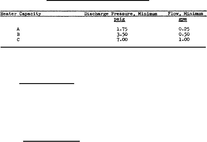
Table V. Coolant Pump Characteristics |
|
||
| ||||||||||
|
|  MIL-H-3177C
in the heater, and shall discharge into the heater jacket. Pump inlet
and outlet (except if the pump is integral) shall be threaded, 3/4 inch NPT,
female, and fitted with hose-to-pipe adapter for 3/4 inch ID hose. The
pump shall have a permanent shaft seal and shall be integral with and
driven by a totally-enclosed rotor, fungus treated in accordance with
3.18. Motor bearings shall be of a type not requiring lubrication or
shall be the lubricated-for-life type. When tested in minus 65" F
ambient temperature with intake head of 20 inches of coolant (see 4.5.4.10),
the pumps for the three capacities of heater shall be as specified in
Table V.
Table V. Coolant Pump Characteristics
Note: The pump, if integral with the heater, shall be as specified in Table
V with the intake head reduced to 6 inches of coolant. Flow readings to
be taken at minus 65" F, 5 minutes after ignition or 5 minutes after heater
indicator light actuates when heater and pump are installed in a closed
circuit system of 5 gallon capacity.
3.11 Coolantt connections. Quick-disconnect couplings shall be provided
at the coolant inlet and outlet of the heater. Unless otherwise] specified
(see 6.2), the couplings shall be 3/4 inch IPS external type with self-
sealing valves, equal to and Interchangeable with model VEN12 as --
ufactured by Snap-Tite, Incorporated, Union City, PA. A male half-coupling
shall be installed on the coolant outlet and a female half-coupling on the
inlet. The mating half-couplings for these shall be furnished and shall
have adapters for 3/4-inch ID hose. The coolant outlet shall also provide
a pressure relief valve adjustable from 10 to 40 psig opening-pressure and
a vent to bleed trapped air from the heater jacket.
3.12 Combustion air inlet. The combustion air inlet shall be circular
and shall provide within the dimensions specified in Table I a 3/4-inch-
long neck for attachment of a duct, but shall provide a snap-on screened
cover for this opening. When specified (see 6.2), an electrically-actuated
poppet valve or damper shall also be furnished which will provide a dust-
tight closure when the heater is not operating but will be open wherever
the blower is running. This damper need not be confined within the overall
dimensions prescribed in Table I.
9
|
|
Privacy Statement - Press Release - Copyright Information. - Contact Us |
