 |
|||
|
|
|||
| ||||||||||
|
|  MIL-I-19028E(OS)
Recovery time shall be measured with suitable calibrated equipment (such
as an oscillograph in conjunction with a frequency-to-voltage converter)
and shall meet the requirements of 3.3.1.3.9.
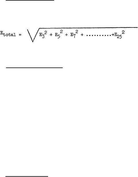
4.5.7 Harmonic voltages. Start and operate the inverter as specified
in 4.4.4.1, 4.4.4.2, 4.4.4.3, and 4.4.4.4. Using a wave analyzer con-
nected across the AB phase, measure the individual odd harmonics up to
and including the twenty-fifth. The harmonic voltages shall not exceed
the limits specified in 3.3.1.3.6. Total harmonic content is defined
as:
where the subscript denotes the harmonic and all voltages are measured
in the same units as the fundamental component.
4.5.8 Radiated interference
4.5.8.1 The inverter shall be tested for sine wave and random noise
interference e.
4.5.8.2 The frequency shall be scanned from 14 to 250 kHz, and meas-
urements shall be made at each frequency at which a peak occurs.
4.5.8.3 The inverter hookup and the determination of interference
type shall be the same as given in 4.4.8.3 and 4.4.8.4 for the conducted
interference test.
4.5.8.4 A 41-inch rod antenna shall be positioned vertically dis-
tance of 3 feet from the closest edge of the inverter. The inverter
shall be placed on 3/4 inch plywood with a bond to a ground plane.
Antennas shall be rotated around the inverter for maximum interference
meter reading.
4.5.8.5 The inverter load during the test shall be the same as given
in 4.4.8.3.7 for the conducted interference tests.
4.5.9 Start-stop life. Start the inverter as specified in 3.3.1.2.2.1.
When the inverter has reached a steady state condition, as determined by
the phase AB output voltage, shut off the inverter. When the inverter
has reached a dead stop, repeat the foregoing steps. Repeat the above
for 1000 Hz. The test maybe stopped and the inverter allowed to cool
to ambient temperature at the end of each 85 plus or minus 5 minutes
of cycling. Following the last cycle, the inverter shall meet the re-
quirements of 3.3.3, 3.3.1.3.2, 3.3.1.3.2.1, and 3.3.1.3.3.
22
|
|
Privacy Statement - Press Release - Copyright Information. - Contact Us |
