 |
|||
|
|
|||
| ||||||||||
|
|  MIL-I-48331A(AR)
NOTES on Fig. 6 and 7
1) All pulse magnitudes are equal to VDD, except on pin 4
as shown in Fig 6 (The input voltage levels applied to the
input terminal 4 during the sequence test must be the max.
and min. LVD voltages specified in Table II for all values
of supply voltages (VDD)).
2) All pulse counts are referenced to the zero start time.
One pulse counts is equal to one pulse of the oscillator
(pins 1-2). Pulses shall be positive, with an amplitude
equal to VDD and 524, 288.
Pulse Width =
l microsecond min.
1 microsecond max.
Rise Time =
Decay Time =
1 microsecond max.
3) The I.C. shall function in accordance with this specifi-
cation when pulsed with clock pulse recurrence rates between
zero and 20 kilohertz. Function above 20 kilohertz is
acceptable.
4)
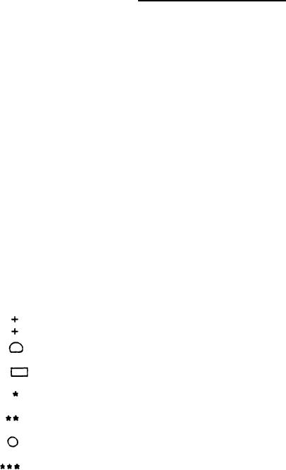
Symbol Terminology:
4.5V)
Pulse width is 2.0 micorseconds (3.0V VDD
Pulse width is 20 microseconds
Pulse width is one input pulse
Repetitive pulse corresponding to input pulses
Pulses at 2X base input frequency
Removal of a high signal, not an applied low signal
VDD rise time shall be set to 1 millisecond and 500
millisecond in successive tests. Ground all IC pins
when VDD=0 (Between tests)
32
|
|
Privacy Statement - Press Release - Copyright Information. - Contact Us |
