 |
|||
|
Page Title:
Table II. Quality Conformance Tests and Examinations and AQL |
|
||
| ||||||||||
|
|  MIL-I-82532 (OS)
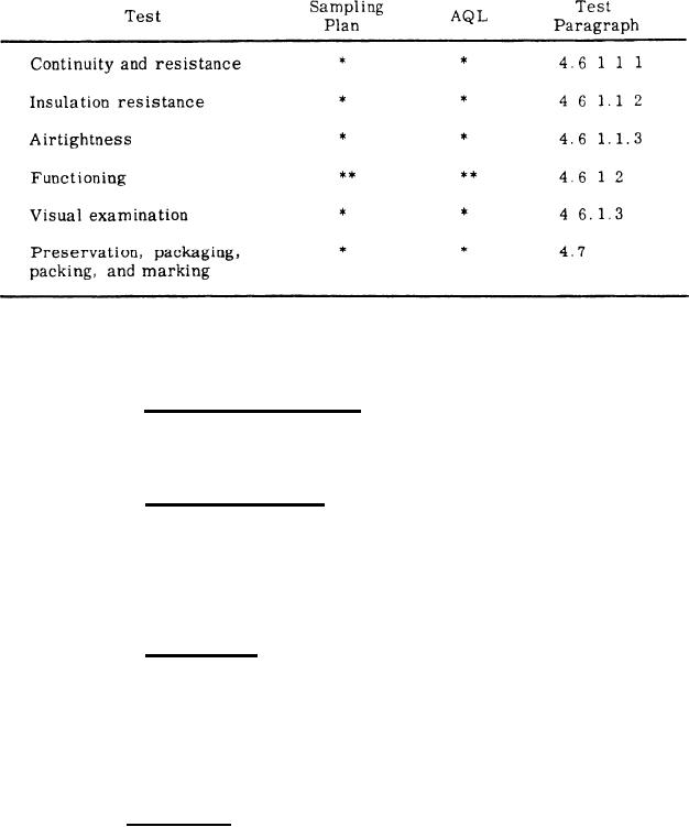
Table II. Quality Conformance Tests and Examinations and AQL
*One-hundred percent inspection; defect is cause for rejection of individual
unit.
** MIL-STD-105D, Special Inspection Level S4; zero defects accepted.
4 . 6 . 1 . 1 . 1 Continuity and resistance. Using the ohmmeter specified in
4.4.la, measure the resistance of each blue-white circuit of the exposed igniter
cable leads. The electrical circuits shall be continuous and the resistances shall
be not less than 0.15 ohm nor greater than 0.22 ohm.
4 . 6 . 1 . 1 . 2 Insulation resistance. Using the megohmmeter specified in
4.4.1b, measure the resistance between the exposed igniter cable leads, shorted
together, and the igniter case. The applied potential shall be 500 plus or minus
50 volts DC, applied for not less than 5 seconds. The resistance between the
shorted leads and the case shall be not less than 20 megohms. This test shall be
performed prior to humidity test (4.5.1.4), fungus test (4.5.1.5), and salt spray
t e s t (4.5.1.6).
Airtightness. Immediately prior to assembly, the igniter case
4.6.1.1.3
shall be thoroughly purged with an inert indicator gas. Subsequent assembly
operations shall be conducted so as to retain a substantially pure atmosphere
of inert gas inside the igniter. Within 20 minutes after sealing, the igniter shall
be placed in a partial vacuum equivalent to 25.84 plus or minus 0.50 inches of
mercury, absolute, and subjected to leak examination using the leak detector
specified in 4.4.1c. The leak rate of the igniter shall be not greater than 0.0001
cubic centimeter per second.
4 . 6 . 1 . 2 Functioning. Subject the igniter to functioning tests using the test
equipment specified in 4.4.1d through 4.4.lg. The light meter shall be positioned
with respect to the igniter as shown in Figure 1.
10
|
|
Privacy Statement - Press Release - Copyright Information. - Contact Us |
