 |
|||
|
|
|||
| ||||||||||
|
|  MIL-M-17059A(SHIPS)
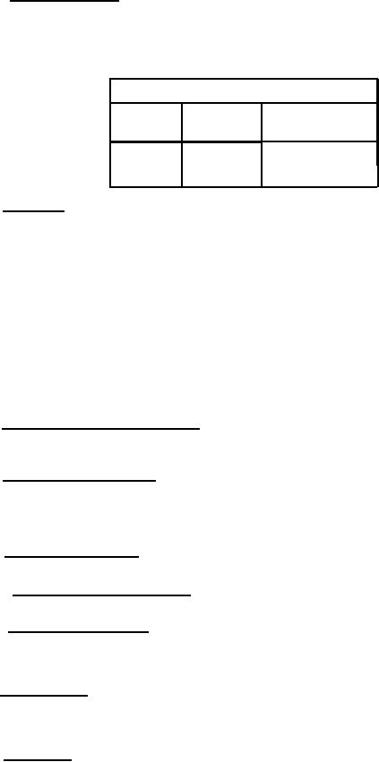
3.5.1.5 Mechanical balance. - When tested as specified in 4.3.4.5, the maximum allowable amplitude
in inches shall be as specified in table X. Unless otherwise specified (see 6.1), the degree of balance shall
be standard in accordance with table X. (For submarine applications, see 3.5.1.17.5.)
Table X - Mechanical balance.
Maximum allowable total amplitude
Super-precision
Precision
Standard
balance
balance
balance
Inch
Inch
Inch
0.0002
0.001
0.0005
Motors shall be designed to operate satisfactory under the following conditions:
3.5.1.6 Inclination. -
(a) Horizontal motors:
(1) For sleeve bearing motors:
a. Shaft inclined 15 degrees, front end low.
b. Shaft inclined 15 degrees, rear end low.
c. Shaft horizontal, motor base tilted 15 degrees to right.
d. Shaft horizontal, motor base tilted 15 degrees to left.
(2) For ball bearing motors:
a. Shaft inclined 15 degrees, front end low.
b. Shaft inclined 15 degrees, rear end low.
(b) Vertical motors:
(1) For sleeve or ball bearing motors:
a. Fifteen degrees from their normal position in any direction.
(c) All motors shall be suitable for operation where a ship is rolling 45 degrees to either side.
(d) Sleeve bearing motors shall be tested as specified in 4.3.4.15.
3.5.1.7 Methods of attaching fans to shaft. - Fans not an integral part of the shaft shall be secured
in such a manner as to preclude their becoming loose when the motor is subjected to high-impact shock
test.
3.5.1.8 Frame and rotor marking. - The manufacturer's name or symbol and identification numbers
shall be stamped or otherwise permanently marked in the solid metal of the frame underneath (covered by)
the main identification plate. For universal motors the part number, or other information sufficient to
completely identify one rotor, shall be stamped or otherwise permanently marked on the shaft or rotor core.
The marking of armatures shall identify the manufacturer and the style and type of motor.
3.5.1.9 Thread cutting screws. - Thread cutting screws (self-tapping screw) shall not be used to
secure any part of the motor.
3.5.1.10 Securing brush holder support. - The support shall be secured in such a manner as to pre-
vent loosening of the support under shock or vibration.
3.5.1.11 Securing terminal leads. - A lead clamp shall be provided on all motors. The method of
fastening shall be such that no strain from the outside can come upon the connections within the motor
frame. The use of friction rubber bushings, unclamped, is not a suitable method of securing such leads.
Sealing compounds for anchoring leads shall not be used (see 3.1.23. 3).
3.5.1.12 Brush holders. - Brush holders shall be readily accessible for adjustment and renewal of
brushes and springs. The construction shall also provide for maintaining the spacing of the various holders
and means shall be provided to prevent loosening and shifting of brush holders under vibration and spring
pressure.
3.5.1.13 Capacitors. - For capacitor-start motors, the capacitor shall be interchangeable with a
Military type if practical.
17
|
|
Privacy Statement - Press Release - Copyright Information. - Contact Us |
