 |
|||
|
|
|||
| ||||||||||
|
|  MIL-M-17059A(SHIPS)
measurements shall be corrected to 25C. Corrections shall be made on the basis of insulation resistance
doubling for each 15C. decrease in temperature. The relative humidity at the time of the test shall be
measured and recorded.
40.4.2 Dielectric - normal potential. - A potential of normal rated voltage shall be applied for a period
of 1 minute between isolated circuits and between each circuit and ground to test their insulation.
40.4.3 Capacitance and dissipation factor. - The capacitance and dissipation factor shall be measured
with the capacitance test bridge and the values shall be read directly from the bridge. The capacitance e and
dissipation factor between each winding and ground and between each of the windings shall be made.
40.4.4 Temperature. - The temperatures of the windings shall be measured by method 2. Thermo-
meters, thermocouples, or ammeters shall be used in adjusting the temperature and keeping it constant.
To measure the temperature by method 2, a bench mark or the cold resistance shall be set up by measuring
the resistance at room temperature and recording this value. When the operating temperature is to be
checked, a stop watch shall be started the instant the power is shut off, the ohmmeter bridge shall be con-
nected as quickly as possible and then simultaneous readings of resistance and time shall be taken. This is
usually a two man job. One man sets the bridge at regular intervals of resistance readings and calls "read"
when the galvanometers of the bridge swings through zero. The other man reads and records the elapsed
time to each "read" signal. This data shall be plotted and the value of resistance, obtained by extrapolating
to zero time, shall be used with bench mark values to calculate the operating temperature. It is apparent
that the sooner the first point is taken the greater will be the precision of measurement. The maximum time
between power shut off and the first resistance reading shall be 30 seconds. This method is always desirable
and for high temperature it becomes a "must", since the temperature drop is so rapid. In making the calcula-
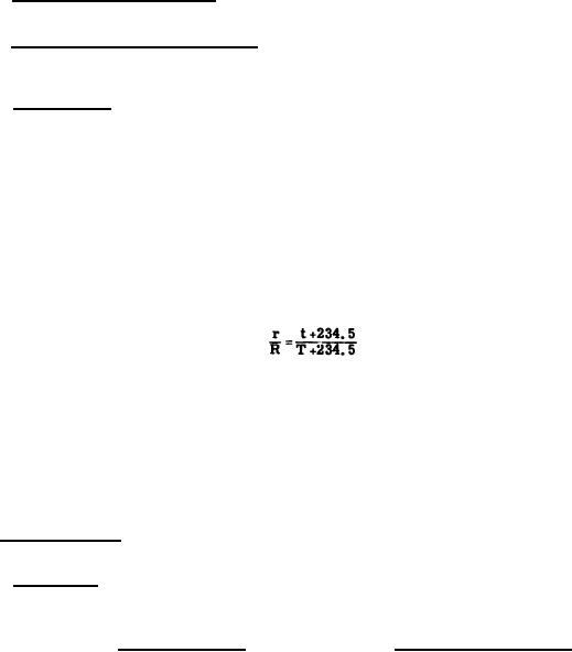
tion, any of several formulae may be used. However, the following form is preferred
Where:
r
=
low or cold resistance in ohms.
R
=
high or hot resistance in ohms.
coil temperature (cold) in0 0C.
t
=
coil temperature (hot) in C.
T
=
NOTE: It is also advisable to check the bench mark or cold resistance values at regular intervals because
of the increase in resistance of the copper due to aging.
40.5 Test procedures. - The motors shall be tested in accordance with the procedures specified in
40.5.1 and 40.5.2.
40.5.1 All motors. - All motors presented for test shall have satisfactorily passed the following
periodic tests specified in table XIV. After completion of these tests a potential of rated voltage shall be
applied as specified in 40.4.1.
Applicable test paragraph
Description of test
Resistance (cold)
4.3.4.2
Dynamic balance
4.3.4.5.1
End play
4.3.4.6.2
No-load input
4.3.4.7
Pull-up, breakdown and lock-rotor torque
4.3.4.8
Dielectric strength
4.3.4.9
Heat run
4.3.4.11
Electrical balance
4.3.4.12
Weight
4.3.4.13
Load test
4.3.4.14
Inclined operation
4.3.4.15
Shock
4.3.4.16
Encapsulation
4.3.4.17
43
|
|
Privacy Statement - Press Release - Copyright Information. - Contact Us |
