 |
|||
|
Page Title:
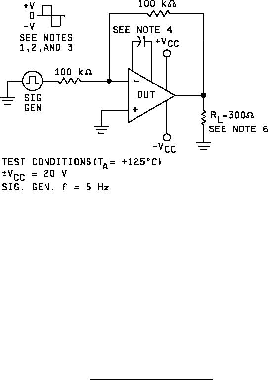
Figure 7. Test circuit, burn-in and operating life test. |
|
||
| ||||||||||
|
|  MIL-M-38510/101H
NOTES:
1. V = 3.0 V for device types 01, 03, 04, and 06.
2. V = 0.5 V for device types 02 and 08.
3. V = 1.0 V for device types 05 and 07.
4. A 30 pF compensation capacitor is required for types 03, 04, 05, and 06.
5. Both halves as above for dual amplifiers, types 02, 05, 06, and 08.
6. For device types 04 and 06, RL = 1500 Ω.
7. All resistor tolerances are 5 percent and shall not exceed its branded value due to use, heat or age.
FIGURE 7. Test circuit, burn-in and operating life test.
32
|
|
Privacy Statement - Press Release - Copyright Information. - Contact Us |
