 |
|||
|
|
|||
| ||||||||||
|
|  MIL-M-38510/101H
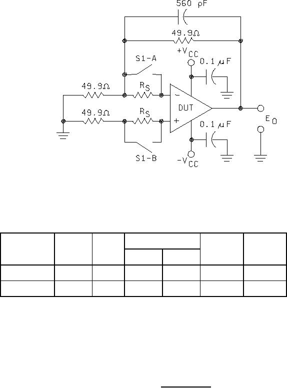
Noise
Symbol
S1
Measure
Measured
Parameter
equation
units
(Referred to
Value
Units
input)
V rms
Broadband
Closed
mV rms
N1(BB)
E0
E0 / 1000
V pk
Popcorn
Open
mV pk
N1(PC)
E0
E0 / 1000
NOTES:
RS = 20 kΩ for device types 01, 02, 07, and 08; RS = 100 kΩ for device types 03, 04, 05, and 06.
1.
2.
E0 is measured using an RMS voltmeter with a bandwidth of 10 Hz to 5 kHz and a peak detector
simultaneously. Monitor the peak test for a minimum of 15 seconds. The loop bandwidth shall be
at least 5 kHz.
FIGURE 10. Noise test circuit.
35
|
|
Privacy Statement - Press Release - Copyright Information. - Contact Us |
