 |
|||
|
Page Title:
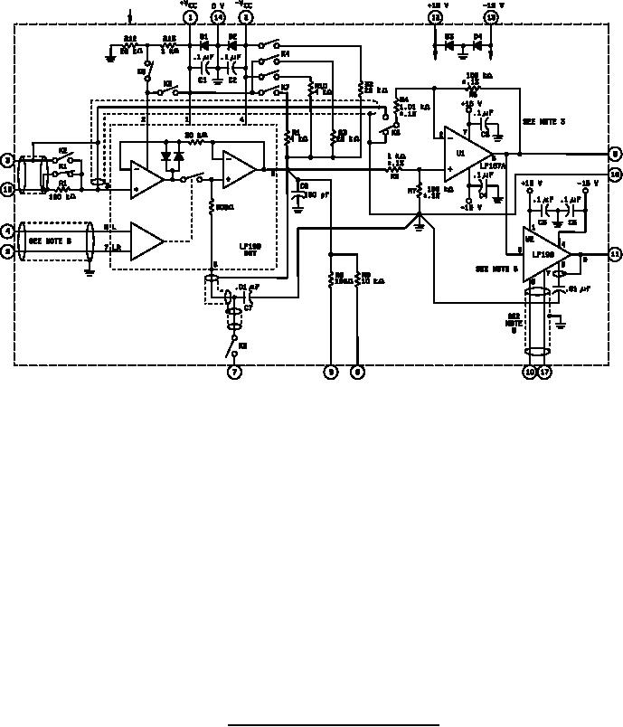
Figure 3. Test circuit for static and dynamic tests. |
|
||
| ||||||||||
|
|  MIL-M-38510/125B
NOTES:
1.
Last component designations are R13, C9, U2, D4, and K8
All resistors are 1 % film unless otherwise stated.
2.
3.
U1 offset error shall be measured with pin 9 grounded and the device under test (D.U.T.) removed.
This error shall be removed in the software calculations.
4.
Relay control inputs are not shown.
A speed-up circuit is required in series with the logic input for rise times greater than 0.5 s.
5.
The adapter S/H U2 is required for TA = 125C testing of some parameters.
6.
FIGURE 3. Test circuit for static and dynamic tests.
13
|
|
Privacy Statement - Press Release - Copyright Information. - Contact Us |
