 |
|||
|
Page Title:
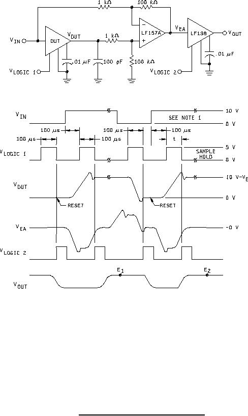
Figure 9. Acquisition time test circuit and wavforms. |
|
||
| ||||||||||
|
|  MIL-M-38510/125B
NOTES:
1. Acquisition time is equal to the logic sample pulse width which yields an output error from steady state
of 10 mV at the device under test (D.U.T.) output or 1 V at the differential amp output (for example;
pulse width t = taq when E1 E2 = 0.1 V).
2. Only the 0 V to +10 V step is shown. The other transitions as per figure 10 shall also be tested.
FIGURE 9. Acquisition time test circuit and wavforms.
19
|
|
Privacy Statement - Press Release - Copyright Information. - Contact Us |
