 |
|||
|
|
|||
| ||||||||||
|
|  MIL-M-38510/125B
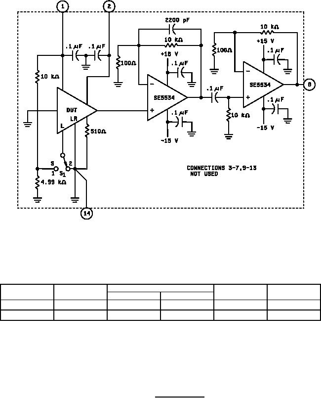
Symbol
S1
Measure
Input Noise
Units
Value
Units
Equation
Vrms
1
Eo
mVrms
en(S)
en(S) = 0.1 Eo
Vrms
2
E0
mVrms
en(H)
en(H) = 0.1 E0
NOTES:
1. The circuit components are designed to provide an effective "brickwall" bandwidth from 10 Hz to 10 kHz.
2. Measurement should be made with a true rms voltmeter with at least 20 kHz bandwidth.
3. The filter pole frequencies are related to the effective noise pass band frequencies as follows:
fLE = 2/š x fLP; fHE = š/2 x fHP.
FIGURE 17. Noise test circuit.
27
|
|
Privacy Statement - Press Release - Copyright Information. - Contact Us |
