 |
|||
|
Page Title:
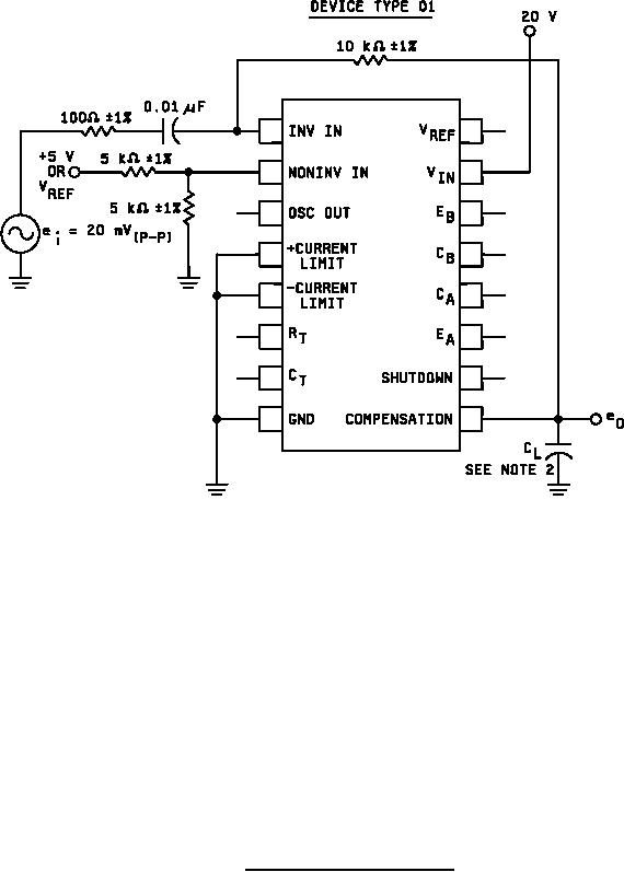
Figure 5. Unity gain bandwidth test circuit. |
|
||
| ||||||||||
|
|  MIL-M-38510/126C
NOTES:
1. GBW is measured by increasing signal frequency (starting at 100 kHz) until eO = 20 mV(P-P).
The frequency at which this occurs is GBW.
2. (CL) capacitance load = 20 pF, -10%, on eO including scope probe and jig capacitance.
3. Alternative method: Set signal frequency (ei) to the GBW minimum limit if eO ≥ 20 mV(P-P) then
GBW is ≥ the minimum limit.
FIGURE 5. Unity gain bandwidth test circuit.
28
|
|
Privacy Statement - Press Release - Copyright Information. - Contact Us |
