 |
|||
|
Page Title:
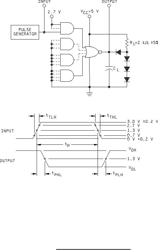
Figure 3. Switching time test circuit and waveforms. |
|
||
| ||||||||||
|
|  MIL-M-38510/304C
NOTES:
1. The pulse generator has the following characteristics: PRR ≤ 1 MHz,
tTLH ≤ 15 ns, tTHL ≤ 6 ns, tp = 0.5 s, and ZOUT ≅ 50Ω.
2. CL = 50 pF 10%, including scope probe, wiring, and stray capacitance, without package in test fixture.
3. All diodes are 1N3064 or equivalent.
4. Voltage measurements are to be made with respect to network ground terminal.
5. Dashes refer to device type 02.
FIGURE 3. Switching time test circuit and waveforms.
8
|
|
Privacy Statement - Press Release - Copyright Information. - Contact Us |
