 |
|||
|
Page Title:
Figure 2. Truth tables and timing diagrams Device type 06 |
|
||
| ||||||||||
|
| 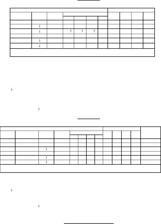 MIL-M-38510/306E
Device type 06
INPUTS
OUTPUTS
MODE
PARALLEL
QB
QC
QD
CLOCK
SERIAL
QA
CONTROL
A
B
C
D
H
H
X
X
X
X
X
QA0
QB0
QC0
QD0
H
X
a
b
c
d
a
b
c
d
H
X
QB
QC
QD
d
QBn
QCn
QDn
d
L
H
X
X
X
X
X
QA0
QB0
QC0
QD0
L
H
X
X
X
X
H
QAn
QBn
QCn
L
L
X
X
X
X
L
QAn
QBn
QCn
When the output control is low, the outputs are disabled to high impedance state.
however, sequential operation of the registers is not affected.
+
Shifting left requires external connection of QB to A, QC to B, and
QD to C. Serial data is entered to input D.
H = high level (steady state), L = low level (steady state)
X = irrelevant (any input, including transitions)
= transition from high to low level.
a, b, c,d = the level of steady state input at inputs A, B, C, or D, respectively.
QA0, QB0, QC0, QD0 = the level of QA, QB, QC, or QD, respectively, before the
indicated steady state input conditions were established.
QAn, QBn, QCn, QDn = the level of QA, QB, QC, or QD, respectively, before the
most recent transition of the clock.
Device type 07
CASCADE
INPUTS
3 STATE OUTPUTS
OUTPUT
PARALLEL
LOAD/SHIFT
CLEAR
QB
QC
QD
CLOCK SERIAL
QA
QD'
CONTROL
A
B
C
D
L
X
X
X
X
X
X
X
L
L
L
L
L
H
H
H
X
X
X
X
X
QA0 QB0
QC0
QD0
QD0
H
H
X
a
b
c
d
a
b
c
d
d
H
L
H
X
X
X
X
X
QA0 QB0
QC0
QD0
QD0
H
L
H
X
X
X
X
H
QAn
QBn
QCn
QCn
H
L
L
X
X
X
X
L
QAn
QBn
QCn
QCn
When the output control is low, the outputs are disabled to high impedance state.
however, sequential operation of the registers is not affected.
H = high level (steady state), L = low level (steady state),
X = irrelevant (any input, including transitions)
= transition from high to low level.
QA0, QB0, QC0, QD0 = the level of QA, QB, QC, or QD, respectively, before the
indicated steady state input conditions were established.
QAn, QBn, QCn, QDn = the level of QA, QB, QC, or QD, respectively, before the
most recent transition of the clock.
FIGURE 2. Truth tables and timing diagrams - Continued.
20
|
|
Privacy Statement - Press Release - Copyright Information. - Contact Us |
