 |
|||
|
Page Title:
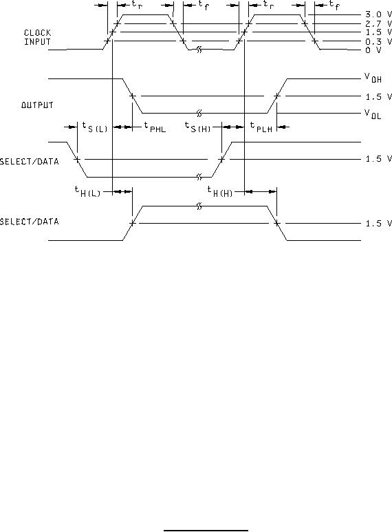
Figure 4. Switching test circuit-cont. |
|
||
| ||||||||||
|
|  MIL-M-38510/350A
NOTES:
1. Pulse generator has the following characteristics: tr = tf ≤ 2.5 ns, PRR ≤ 1 MHz, ZOUT ≈ 50Ω.
2. Inputs not under test are at 2.7 V or GND as specified in table III.
3. CL = 50 pF 10%. including scope, probe, wiring, and stray capacitance, without package in test fixture.
4. Voltage measurements are to be made with respect to network ground terminal.
5. RL = 500Ω 5%.
6. Setup and hold times, rising-edge clock for select input and data input.
FIGURE 4. Switching test circuit - Continued.
12
|
|
Privacy Statement - Press Release - Copyright Information. - Contact Us |
