 |
|||
|
Page Title:
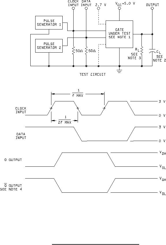
Figure 5. Input clock frequency test circuit (all device types). |
|
||
| ||||||||||
|
|  MIL-M-38510/350A
NOTES:
1. Inputs not under test are at 2.7 V or GND as specified in table III.
2. CL = 50 pF 10% including scope, probe, wiring, and stray capacitance, without package in test fixture.
3. RL = 500Ω 5%.
4. Device type 01 only.
FIGURE 5. Input clock frequency test circuit (all device types).
13
|
|
Privacy Statement - Press Release - Copyright Information. - Contact Us |
