 |
|||
|
Page Title:
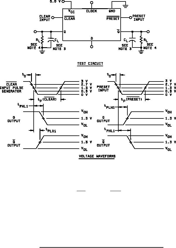
Figure 4. Clear and preset switching test circuit and waveforms (device type 01). |
|
||
| ||||||||||
|
|  MIL-M-38510/371B
NOTES:
1. Clear and preset inputs dominate regardless of the state of clock or D inputs.
2. Clear or preset input pulse charactersistics: tp ( clear ) = 15 ns; tp ( preset ) = 15 ns;
and PRR ≤ 1 MHz; t0 = 6 1.5 ns.
3. CL = 50 pF 10% (including jug and probe capacitance without package in test fixture).
4. RL = 499Ω 1%.
5. When testing clear to output switching, preset input shall have a logical "1" voltage
applied. When testing preset to output switching, clear input shall have a logical
"1" voltage applied (see table III).
6. Voltage measurements are to be made with respect to network ground terminal.
FIGURE 4. Clear and preset switching test circuit and waveforms (device type 01).
19
|
|
Privacy Statement - Press Release - Copyright Information. - Contact Us |
