 |
|||
|
Page Title:
Figure 3. Three-state switching test circuit and waveforms (device type 06) |
|
||
| ||||||||||
|
| 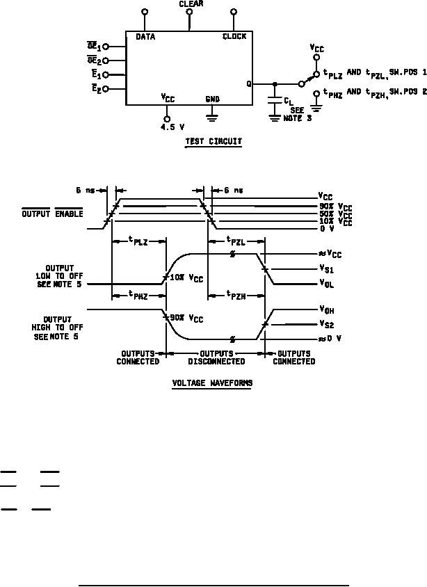 MIL-M-38510/653B
NOTES:
1. OE1 and OE2 pulses are active low and one or both must be active to enable the outputs.
OE1 and OE2 input pulse characteristics are as follows: tr = tf ≤ 6 ns; tpOE1 = tpOE2 ≥ 200 ns.
2.
CL = 50 pF 10 % (including test jig and probe capacitance).
3.
4.
OE1 or OE2 does not affect the sequential operation of the flip-flop.
For tPHZ and tPZH, a 1 kΩ resistor is connected between the output and the GND terminal. For tPZL and
5.
tPLZ, a 1 kΩ resistor is connected between the output and the VCC terminal. VS1 = VOL +0.1 V (VOH-VOL).
VS2 = VOH 0.1 V (VOH-VOL).
FIGURE 3. Three-state switching test circuit and waveforms (device type 06) - Continued.
28
|
|
Privacy Statement - Press Release - Copyright Information. - Contact Us |
