 |
|||
|
Page Title:
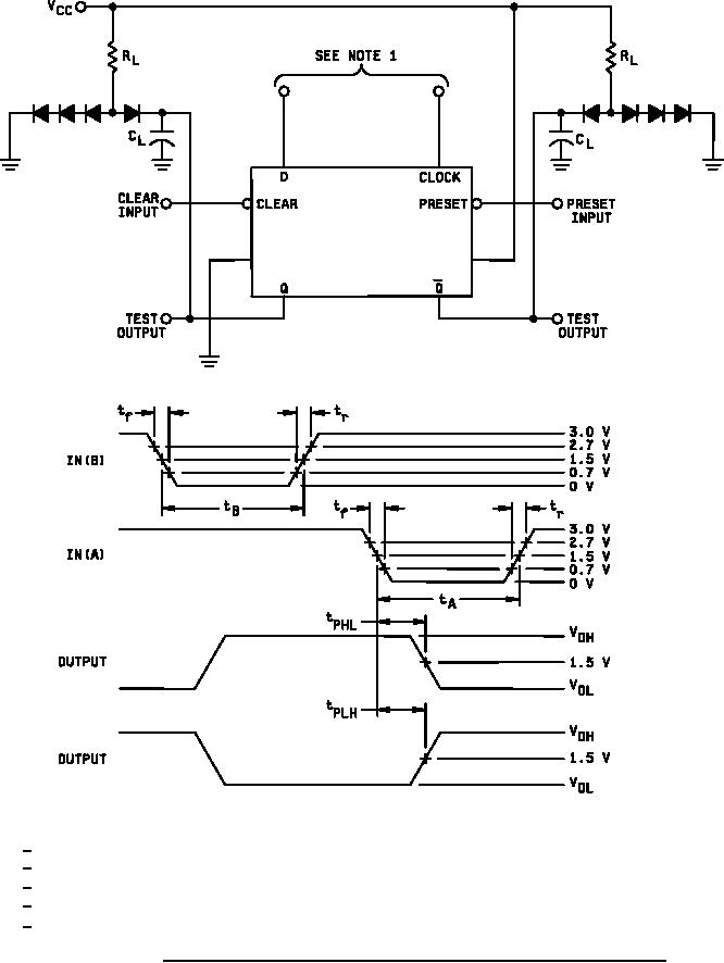
Figure 4. Clear and preset switching time test circuit and waveforms for device type 01. |
|
||
| ||||||||||
|
|  MIL-M-38510/71D
NOTES:
1/ Clear and preset inputs dominate regardless of the state of clock or D inputs.
2/ All diodes are 1N3064 or equivalent.
3/ tf = tr ≤ 2.5 ns, tA = 10 ns 20%, tB = 10 ns 20%, PRR ≤ 1 MHz.
4/ CL = 50 pF 10% including jig and probe capacitance.
5/ RL = 280 Ω 5%.
FIGURE 4. Clear and preset switching time test circuit and waveforms for device type 01.
16
|
|
Privacy Statement - Press Release - Copyright Information. - Contact Us |
