 |
|||
|
Page Title:
Table 3. Group A inspection for device type 02-cont. |
|
||
| ||||||||||
|
| 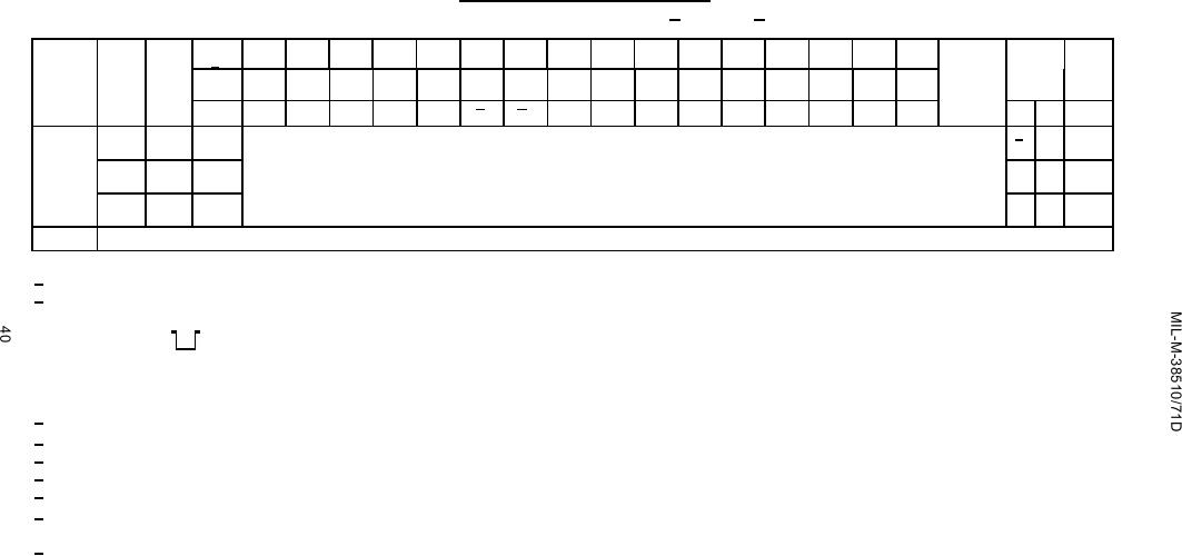 TABLE III. Group A inspection for device type 02 - Continued.
Terminal conditions (pins not designated may be high > 2.0 V, low < 0.8 V, or open).
Case X,2
2
3
4
5
7
8
9
10
12
13
14
15
17
18
19
20
1/
MIL-
Cases
1
2
3
4
5
6
7
8
9
10
11
12
13
14
15
16
Test limits
Unit
Subgroup
Symbol STD-883 E,F
Measured
method Test no. CLK 1
Min Max
terminal
GND
Q2
PRE 2
J2
K2
CLK 2 CLR 2 CLR 1
K1
J1
PRE 1
Q1
Q1
Q2
VCC
10
9/
Fig. 8
156-159
tSETUP
TC = +125C (H)
"
160-163
"
tHOLD
Same tests and terminal conditions as for subgroup 9, except TC = +125C and limits are as shown.
(L)
"
164-167
"
tHOLD
(H)
11
Same tests, terminal conditions, and limits as for subgroup 10, except TC = -55C.
1/ Cases X and 2 terminals not designated are NC.
2/ C = Normal clock pulse.
D=
---5.0 V
---0 V
E = Normal input conditioning is 5.0 V, however, momentary logic "0" may be applied to input
for synchronizing test equipment and preconditioning device under test.
3/
For circuit B, IIL4(min) is -0.7 mA.
4/
For circuit B, IOS(max) is 110 mA.
5/
Only a summary of attributes data is required.
6/
Inputs: A = 2.4 minimum, 8 = 0.4 V.
Outputs: L ≤ 1.5 V, H ≥ 1.5 V.
7/
8/
fMAX, minimum limit specified is the frequency of the input pulse. The output frequency
shall be one-half of the input frequency.
9/
Setup and hold time functionally may be verified by separate tests from propagation delay
tests by monitoring the outputs at specified setup and hold conditions.
|
|
Privacy Statement - Press Release - Copyright Information. - Contact Us |
