 |
|||
|
Page Title:
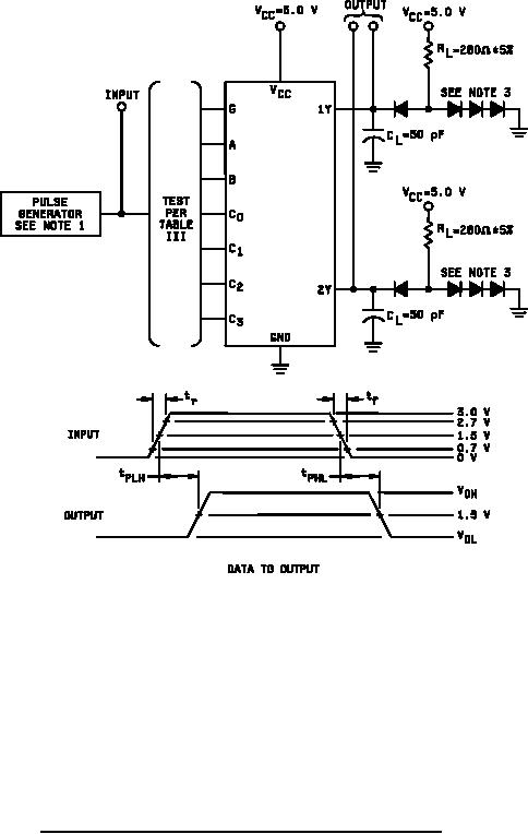
Figure 4. Switching time test circuits and waveforms for device type 02. |
|
||
| ||||||||||
|
|  MIL-M-38510/79D
NOTES:
≤
≤
≈
1. The input pulse has the following characteristics: tr = tf
2.5 ns, PRR
1 MHz, and ZOUT
50 Ω.
2.
CL includes probe and jig capacitance.
3.
All diodes are 1N3064 or equivalent.
4.
Only the output under test needs to be loaded.
FIGURE 4. Switching time test circuits and waveforms for device type 02.
17
|
|
Privacy Statement - Press Release - Copyright Information. - Contact Us |
