 |
|||
|
Page Title:
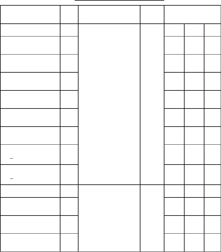
Table 1. Electrical performance characteristics-cont. |
|
||
| ||||||||||
|
|  MIL-M-38510/9E
TABLE I. Electrical performance characteristics - Continued.
Device
Limits
Conditions
Test
Symbol
type
-55C ≤ TC ≤ +125C
unless otherwise specified
VCC = 5.0 V, CL = 50 pF 10%
Maximum clock frequency
fMAX
04
14
MHz
RL = 400 Ω 5%
Propagation delay time,
tPLH1
(See figure 7)
10
40
ns
low to high level, load input
to any output
Propagation delay time,
tPHL1
11
60
ns
high to low level, load input
to any output
Propagation delay time,
tPLH2
6
37
ns
low to high level, clock input
to any output
Propagation delay time,
tPHL2
10
47
ns
high to low level, clock input
to any output
Propagation delay time,
tPLH3
5
27
ns
low to high level, H input
to QH output
Propagation delay time,
tPHL3
11
54
ns
high to low level, H input
to QH output
Propagation delay time,
tPLH4
10
41
ns
low to high level, H input
to QH output
Propagation delay time,
tPHL4
10
41
ns
high to low level, H input
to QH output
VCC = 5.0 V, CL = 50 pF 10%
Maximum clock frequency
fMAX
05
18
MHz
RL = 400 Ω 5%
Propagation delay time,
tPHL1
(See figure 8)
7
48
ns
high to low level, output
from clear
Propagation delay time,
tPLH2
7
36
ns
low to high level output
from clock
Propagation delay time,
tPHL2
7
44
ns
high to low level output
from clock
See footnotes at end of table.
8
|
|
Privacy Statement - Press Release - Copyright Information. - Contact Us |
