 |
|||
|
Page Title:
Table 1. Electrical performance characteristics-cont. |
|
||
| ||||||||||
|
|  MIL-M-38510/9E
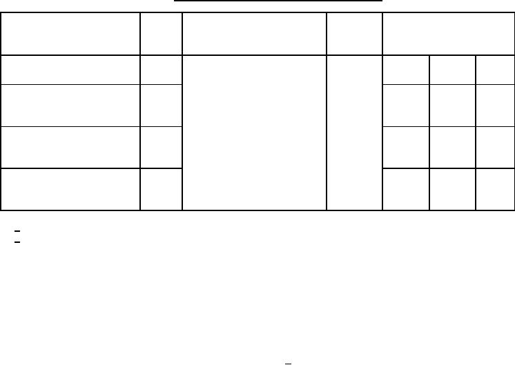
TABLE I. Electrical performance characteristics - Continued.
Device
Limits
Conditions
Test
Symbol
type
-55C ≤ TC ≤ +125C
unless otherwise specified
VCC = 5.0 V, CL = 50 pF 10%
Maximum clock frequency
fMAX
06
24
MHz
RL = 400 Ω 5%
Propagation delay time,
tPHL1
(See figure 9)
7
34
ns
high to low level output
from clear
Propagation delay time,
tPLH2
7
28
ns
high to low level output
from clock
Propagation delay time,
tPHL2
7
34
ns
low to high level output
from clock
1/ Not more than one output should be shorted at a time.
2/ Device type:
01 - With the outputs open, mode control at 4.5 V, clock pulse applied to both clock inputs, ICC is measured
immediately after the application of the clock pulse.
02 - With the outputs open, presets at 4.5 V, ICC is measured with the clock at ground and again with the
clock at 4.5 V.
03 - ICC is measured with outputs open, serial inputs grounded, and a momentary ground, then 4.5 V
applied to clear.
04 - With the outputs open, serial at ground, clock, clock inhibit, and parallel inputs at 4.5 V, ICC is
measured by applying momentary ground, then 4.5 V to shift load prior to measurement.
05 - With all outputs open, inputs A thru D grounded, 5.5. V applied to S0, S1, clear, and the serial inputs,
ICC is tested by applying clock pulse.
06 - With the outputs open, clear at 5.5 V, shift load, J, K , and data inputs grounded, ICC is measured by
applying clock pulse.
9
|
|
Privacy Statement - Press Release - Copyright Information. - Contact Us |
