 |
|||
|
Page Title:
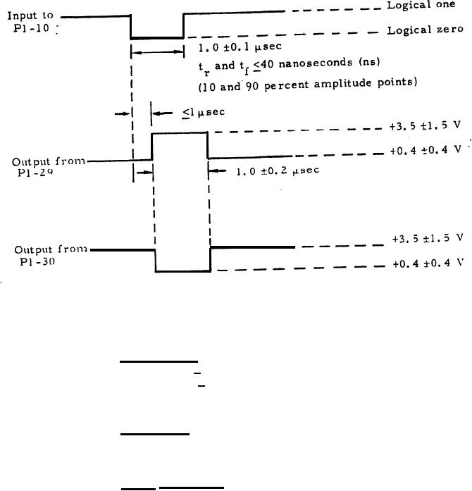
Figure- 1 Reset Signal Wave forms |
|
||
| ||||||||||
|
|  MIL-M-50747(MU)
8 August 1973
Figure- 1 Reset Signal Wave forms
3.3.1.2 Range signal. With no
input signal applied to P1-1, the
output at P1 -3 shall be +5.0 + 1.0 Vdc.
With P1-1 connected to P1-7, the
output at P1 - 3 shall be +0.2 + 0.2 V.
With P1-1 disconnected from P1-7 and
and P1-2 connected to P1-7,the output
at P1-3 shall be +0.2 0.2V.
3. 3.1.3 Test range. With the type-B signals shown in fugure 2
applied to P1-23 and P1-24, the output at P1-6 shall be as shown in
figure 2. (This signal may be recurring.)
3.3.1.4 A-trigger signal. With the type-A signal shown in
figure 3 applied to P1-35, the outputs at P1-17 and P1-16 shall be as
shown in figure 3. (The signal may be recurring.)
5
|
|
Privacy Statement - Press Release - Copyright Information. - Contact Us |
