 |
|||
|
|
|||
| ||||||||||
|
|  MIL-M-50747(MU)
8 August 73
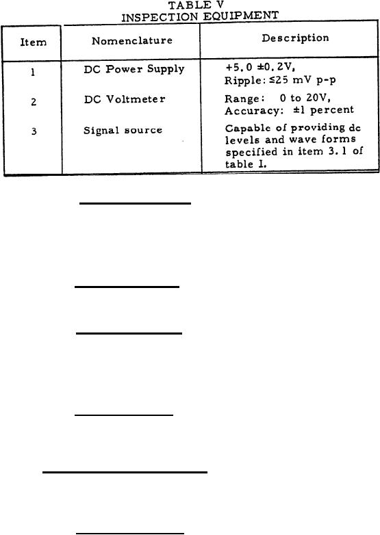
4.6.1.1 Initial conditions. Connect the loads and power to the
assembly as specified in table I.
The MALF 3 buffer logic may be performance tested using
NOTE:
the digital logic type truth-table shown in table VI when
tested at the system level,
4. 6.2 Reset signal test. Apply the digital type-B signal of table 1
to P1-10 as shown in figure 1. Measure the outputs at P1-29 and P1-30
to determine compliance with 3.3.1.1.
4. 6.3 Range signal test. With no input applied to P1-1, measure
the output at P1-3 to determine compliance with 3.3.1.2. Connect P1-1
to P1-7. Measure the output at P1-3 to determine compliance with
3.3.1.2. Disconnect P1-1 from P1-7 and connect P1-2 to P1-7.
Measure the output at P1-3 to determine compliance with 3.3.1.2.
4.6.4 Test range test. Apply the type -B input signal of figure 2
to P1-23 and P1-24. Observe the output at P1-6 to determine compliance
with 3.3.1.3.
4.6.5 A-trigger signal test. Apply the type-A signal of figure 3
to P1-35. Observe the outputs at P1-17 and P1-16 to determine compli-
ance with 3.3.1.4
4.6.6 Video-signal test. Apply the type-A1 input signal of figure 4
to P1-37. Observe the output at P1-19 and P1-18 to determine compliance
with 3. 3. 1. 5
13
|
|
Privacy Statement - Press Release - Copyright Information. - Contact Us |
