 |
|||
|
Page Title:
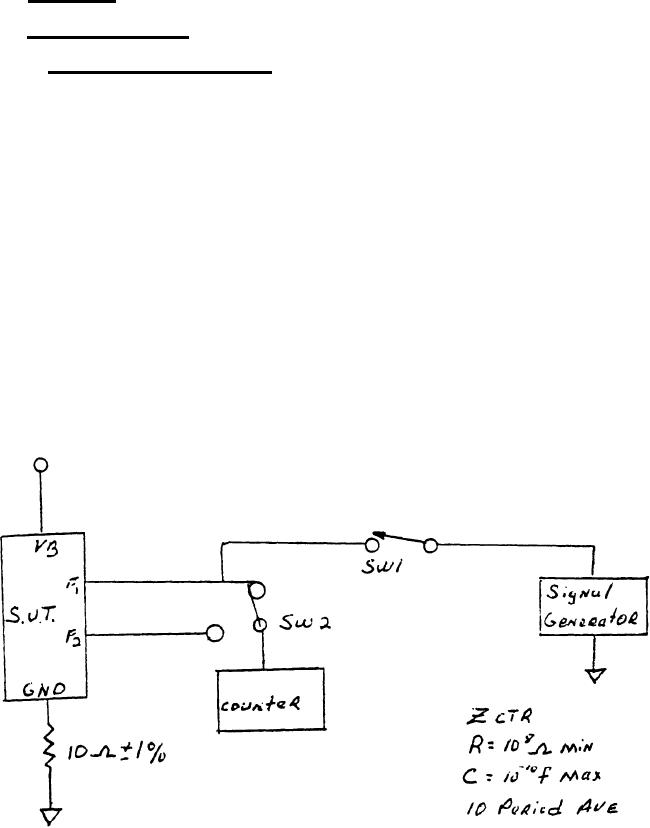
Figure 1. Oscillator Frequency Measurement. |
|
||
| ||||||||||
|
|  MIL-M-70779 (AR)
APPENDIX A
40.1 Table I.
40.2 Test procedure.
40.2.1 Oscillator frequency. The oscillator frequency shall
be measured by connecting the S.U.T. (System Under Test) as shown
in Figure 1. The counter shall have an input impendence of 10 8
ohms or greater (C=10pF maximum) and the measurement shall
represent a ten (10) period average. Frequency of both F1/4 and
Fx shall be measured, and be within the limits of Table 1. Input
F1/4 shall have a minimum of fifteen-hundred (1,500) fast counts
applied and shall stabilize for five-hundred (500) milliseconds
minimum before the measurement is made. Test sequence: 1) Close
SW1/4 and allow fifteen-hundred (1,500) fast counts to enter; 2)
Open SW1 and wait five-hundred (500) milliseconds minimum; 3)
Close SW2 to F1; 4) Measure 10 period average of F1; 5) Close
SW2 to F2; 6) Measure ten (10) period average of F2.
Figure 1.
Oscillator Frequency Measurement.
57
|
|
Privacy Statement - Press Release - Copyright Information. - Contact Us |
