 |
|||
|
|
|||
| ||||||||||
|
|  MIL-P-22497C(OS)
to mere than 200 amperes within a period of not more than ten seconds to
determine the maximum current at which limiting action occurs. Verify
that the output voltage returns to its preset value when the overload is
removed.
4.6.3.12 Series operation. Verify that the outputs of two Type IV(A)
power supplies can be connected series additive to obtain an output volt-
age equal to the sum of The output voltages of the individual power sup-
plies, No interconnection except the series connection of output ter-
minals shall be used.
NOTE
When operating two power supplies with
series-connected outputs, the output
voltage controls shall be varied simul-
taneously to approximately' balance the
voltage and load between the two limits.
4.6.3.13 Verify that the power supply operates as specified for any
comibination of resistive, inductive, capacitive, or rotating inverter
load within load rating of the power supply. The testing of the pre-
production samples for this requirement shall be accomplished using
the actual weapons and test equipment specified in 3.3.2.11. After
testing of the preproduction samples has confirmed that the design is
compatible with the weapons and equipment, this test can be conducted
by the contractor using substitute loads, the designs of which are ap-
proved by the Government procurement agency.
4.6.3.14 Verify that changes in the power supply output voltage
control result in simultaneous changes in the dc output voltage, with
negligible lag.
4.6.3.14.1 Verify that the voltage control is capable of adjusting
the output voltage in the range of 6 to 90 volts within less than one-
half volt.
4.6.3.14.2 Verify that the control of the dc output voltage is linear
within plus or minus 20 degrees of shaft rotation at a minimum of 5 points
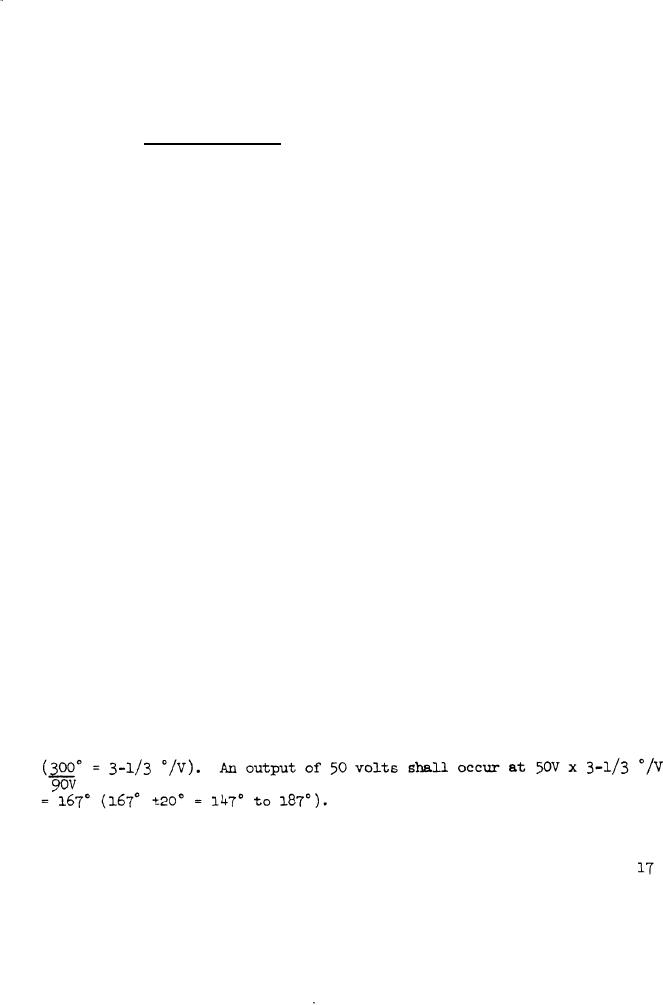
distributed throughout the voltage range. Example: Divide the total
mechanical degrees of shaft rotation (say 300) by the total voltage
range covered (say 5 to 95 = 90 volts) to obtain degrees per volt
|
|
Privacy Statement - Press Release - Copyright Information. - Contact Us |