 |
|||
|
Page Title:
General presentation of performance curves |
|
||
| ||||||||||
|
|  MIL-P-26367A
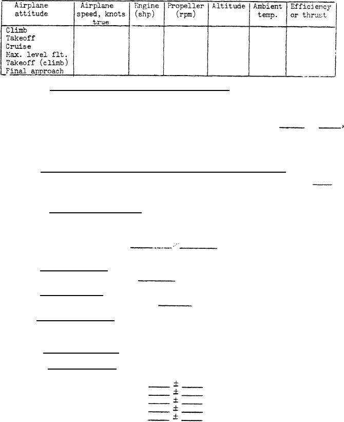
TABLE II.
Estimated aerodynamic performance
3.4.3.1 General presentation of performance curves. - Curves showing propeller
performance, including altitude effects (pressure level and Reynolds' number) where
applicable, at each 10,000-foot increment in altitudes between sea level and 30,000
feet, at each 5,000-foot increment from 35,000 feet to 45,000 feet up to the absolute
altitude of the engine specified herein shall be as shown on figures
to
inclusive. Each curve shows the variation of the net propeller thrust with flight
Mach number for the maximum, military, normal, 90 percent normal, 75 percent normal,
60 percent normal, and idle thru condition. (These curves shall be drawn in accord-
ance with figures 1 and 2. Additional curves may be used when required for clarity.)
3.4.4 Altitude-temperature limits for unfeathering and operation. - The esti-
mated propeller unfeathering and operating limits shall be as shown on figure
.
(The diagram shall be furnished in accordance with figure 1 titled "Temperature range
vs. altitude" of MIL-P-26366.)
3.4.6.1 Airspeed and altitude. - The propeller system shall operate satisfactor-
ily in accordance with this specification within the ambient altitude air temperature
ranges specified in 3.4.4 throughout the following airspeed ranges:
(a) Airspeed
knots
3.4.7 Reverse thrust.- The propeller system shall operate satisfactorily in
the reverse thrust condition up to
lbs.
3.4.8 Static thrust.- The minimum allowble measured static thrust generated
by the propeller shall be not less than
lbs.
* 3.4.9 Power transients.- Characteristics of the propeller system which define
response under power transient conditions shall be furnished as curves basically in
accordance with the fore, shown on figure 3.
3.4.10 Rotational speed.- The rotational speed of the propeller shall be as
follow:
Power conditions
Rpm
Ground idle
Flight idle
Takeoff
Normal
Cruise
5
|
|
Privacy Statement - Press Release - Copyright Information. - Contact Us |
