 |
|||
|
Page Title:
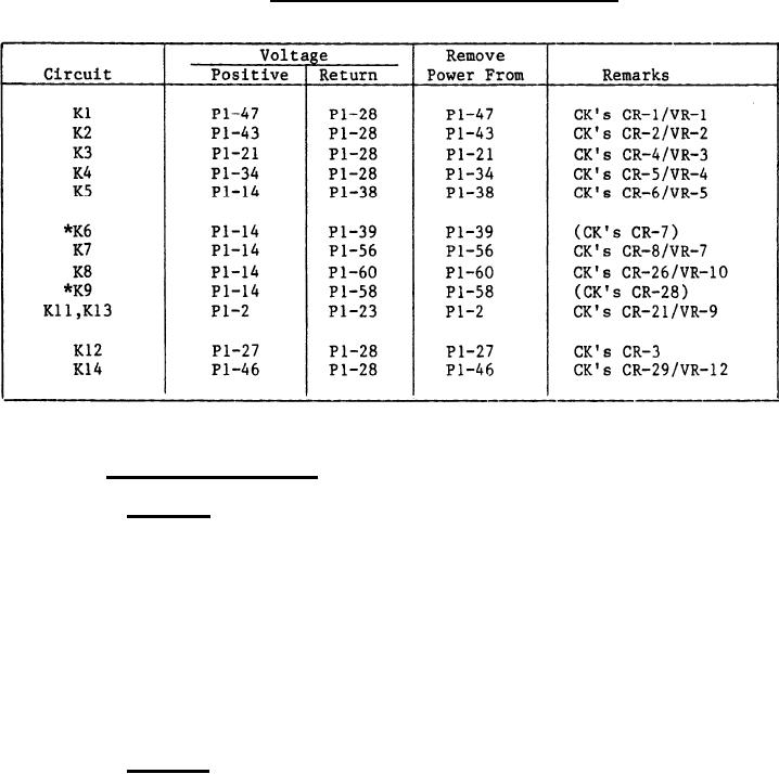
Table VI. Relay transient voltage suppression. |
|
||
| ||||||||||
|
|  MIL-P-62341/2A
TABLE VI.
Relay transient voltage suppression.
*Drop out transient voltage shall be within the range of +30 to -0.9 V dc.
3.5.9 Fire warning circuit.
3.5.9.1 Class 1. With 24 6 V dc connected to pins P1-31 (positive)
and P1-27 (return), connect a test lamp (conforming to MS25237-387) to pins
P1-16 (positive) and P1-18 (return). Connect a second test lamp to pins
P1-26 (positive) and P1-25 (return), with a 1.0 pulse per second (pps)
repetitive positive signal source having an amplitude of 24 6 V dc
connected to pins P1-32 (positive) and P1-27 (return), relays K1O, K11 and
K13 shall latch in and cause the test lamps to flash at the signal source
rate of 1.0 pps. Relays K1O, K11 and K13 shall not de-energize when the
signal source rate of 1.0 pps. Relays K1O, K11 and K13 shall not de-energize
when the signal source is removed from pin P1-32. Relays K1O, K11 and K13
shall deenergize with a momentary interruption of power at pin P1-31 (see
4.8.4.10.1).
3.5.9.2 Class 2. With 24 6 V dc connected to pins P1-46 (positive)
and P1-23 and P1-26 (return), connect a test lamp (conforming to MS25237-387)
to pins P1-31 (positive) and P1-30 (return). Connect a second test lamp to
pins P1-24 (positive) and P1-8 (return). With a 1.0 pulse per second (pps)
repetitive positive signal source having an amplitude of 24 6 V dc
connected to pins P1-2 (positive) and P1-23 (return), the test lamp between
P1-24 and P1-8 shall illuminate steady and the test lamp between P1-31 and
P1-30 shall flash at the signal source rate of 1.0 pps. When the signal
source is removed from P1-2, the lamp between P1-24 and P1-8 shall remain
illuminated and the flashing lamp between P1-31 and P1-30 shall extinguish.
The lamp between P1-24 and P1-8 shall extinguish with a momentary
interruption of power at P1-46 (see 4.8.4.10.2).
6
|
|
Privacy Statement - Press Release - Copyright Information. - Contact Us |
