 |
|||
|
Page Title:
Circuit board assembly test procedure |
|
||
| ||||||||||
|
|  MIL-P-70624A(AR)
4.5.4.11 Circuit board assembly test procedure.
Set MODE switch to OFF.
Connect the sine wave generator
to TB3-1(-) and TB3-11(+).
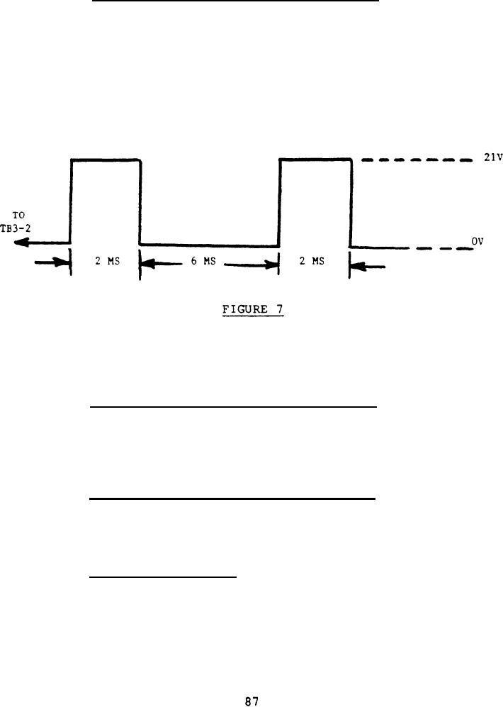
b. Disconnect the proximity sensor and apply Figure 7 to
terminal TB 3-2 (+) and TB 3-1 (-).
c.
Turn MODE switch to "NORMAL".
d. When Figure 7 is applied, observe for the requirements
specified in 3.6.11.
4.5.4.12 Circuit board assembly test procedure.
Turn the MODE switch to "EXTENDED".
a.
b. When Figure 7 is applied, observe for the requirements
specified in 3.6.11.
4.5.4.13 Circuit board assembly test procedure. Disconnect the
oscilloscope and all other test equipment. Turn the MODE switch to
OFF. Disconnect the power supply, the proximity switch, cable and
the transmitter coil assembly. Assemble item 44, "Cover Access:
Test Block" .
4.5.4.14 Ambient tempe rature (75F 10F). The
electronics box components assembly shall be conditioned at the
specified temperature for a minimum of 24 hours prior to testing as
specified in 4.5.4.
|
|
Privacy Statement - Press Release - Copyright Information. - Contact Us |
