 |
|||
|
Page Title:
Table VIII. Group B sampling plan |
|
||
| ||||||||||
|
|  MIL-R-19365D
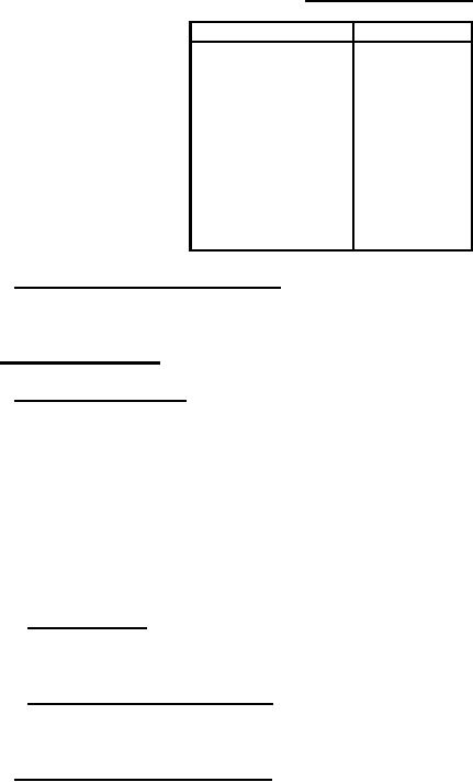
TABLE VII. Group B sampling plan.
Lot size
Sample size
2 to
5
100%
6 to
50
5
51 to
90
7
91 to
150
11
151 to
280
13
281 to
500
16
501 to
1,200
19
1,201 to
3,200
23
3,201 to 10,000
29
10,001 to 35,000
35
35,001 and over
40
4.6.4 Inspection of preparation for delivery . Sample packages and packs and the inspection of the
preservation and packaging, packing, and ma rking for shipment and storage shall be in accordance with
the requirements of section 5 and the documents specified therein.
4.7 Methods of inspection.
4.7.1 DC resistance (see 3.7). The dc resistance shall be measured in accordance with method 303 of
MIL-STD -202 and as specified in 4.7.1.1 and 4.7.1.2. The following details and exceptions shall apply:
a. Measuring apparatus: Different types of measuring test equipment (multimeters, bridges, or
equivalent) are permitted to be used on the initial and final readings of this test, provided the
equipment is the same style, model, or it can be shown that the performance of the equipment is
equivalent or better.
b. Test voltage: Measurements of resistance shall be made by using a dc potential resulting in not
more than 1 percent of rated wattage (see 3.6). The voltage used for the initial measurement shall
be used for all subsequent measurements.
4.7.1.1 Total (see 3.7.1). The dc resistance shall be measured as specified in 4.7.1 between the two
fixed end terminals. For the initial tolerance determination, the total resistance shall be measured with
the adjustable terminal removed from the resistor.
4.7.1.2 Maximum engageable (see 3.7.2). The dc resistance shall be measured as specified in 4.7.1,
between each fixed end terminal and the adjustable terminal, with the latter positioned farthest from the
fixed end terminal, while still engaging the bare resistance wire.
4.7.2 Visual and mechanical examination. Resistors shall be examined to verify that the materials,
design, construction, physical dimensions, marking and workmanship are accordance with the applicable
requirements (see 3.1, 3.3 to 3.5 incl., and 3.19 to 3.22 incl.).
19
|
|
Privacy Statement - Press Release - Copyright Information. - Contact Us |
