 |
|||
|
Page Title:
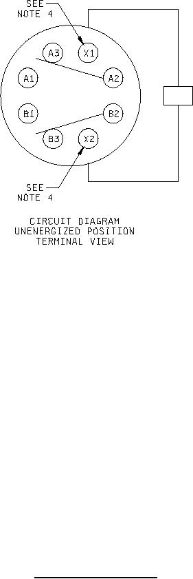
Figure 1. Dimensions and configuration - Continued |
|
||
| ||||||||||
|
|  MIL-R-5757/8F
Inches
mm
.040
1.02
.125
3.18
.20
5.1
.234
5.94
.52
13.2
.65
16.5
.73
18.5
.875
22.22
1.08
27.4
1.35
34.3
NOTES:
1. Dimensions are in inches.
2. Unless otherwise specified, tolerance is .005 (0.13 mm).
3. Metric equivalents are given for general information only.
4. Indicated terminals shall be identified with contrasting beads.
5. Mounting screw head clearance shall be provided so that the relay may be mounted using a round head
machine screw having .202 (5.13 mm) nominal head diameter. The mounting surface shall be flat with a
minimum .218 (5.54 mm) diameter, and concentric with the mounting hole.
6. Circuit diagram shown on relay is terminal view.
FIGURE 1. Dimensions and configuration - Continued.
2
|
|
Privacy Statement - Press Release - Copyright Information. - Contact Us |
