 |
|||
|
Page Title:
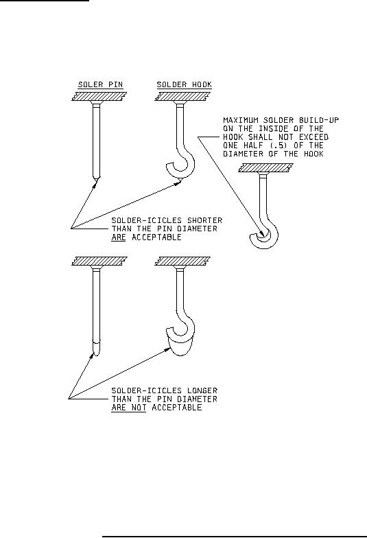
Figure 2. Solder-dip acceptability criteria (solder-icicle length limits) |
|
||
| ||||||||||
|
|  MIL-R-5757H
3.4.7 Terminals (see 3.1). Terminals shall be as specified herein. Manufacturer may supply hot
solder dipped terminals provided that the hot solder dipping process has been approved by the qualifying
activity and when specified on the individual order (see 6.2.1a). Solder dipped terminals may be .002
inch (0.05 mm) larger than the maximum dimension specified (see 3.1). Icicles are a normal result of
the hot solder dip process and shall not be grounds for rejection (see figure 2).
NOTES:
1. No solder is allowed on the header surface. Components (relay terminals) after solder-dip shall
be capable of meeting method 208 of MIL-STD-202, solderability requirements.
2. Solder-coat thickness shall be .0001 inch (.003 mm) minimum.
FIGURE 2. Solder-dip acceptability criteria (solder-icicle length limits).
6
|
|
Privacy Statement - Press Release - Copyright Information. - Contact Us |
