 |
|||
|
Page Title:
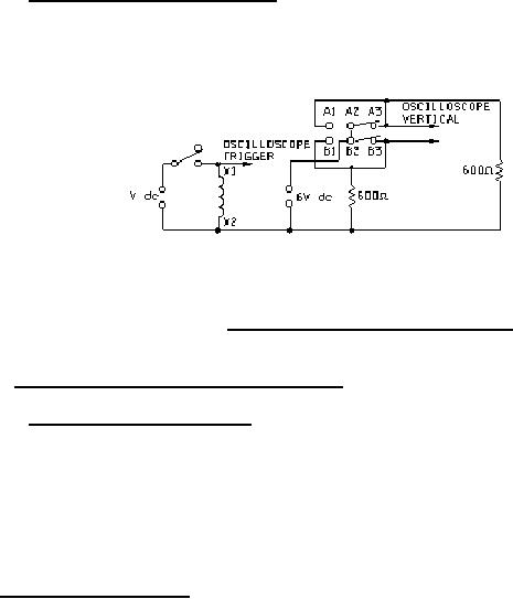
Figure 7. Typical break before make test circuits |
|
||
| ||||||||||
|
|  MIL-R-5757H
4.6.8.4.1 Break before make (see 3.10.4.1). The circuit shown on figure 7 or an equivalent circuit
approved by the qualifying activity shall be used to monitor contact position.
FIGURE 7. Typical break before make test circuits.
4.6.8.5 Contact dynamic characteristics (see 3.10.5).
4.6.8.5.1 Contact bounce (see 3.10.5.1). Contact bounce shall be measured on each contact set
using an oscilloscope or other acceptable means approved by the qualifying activity. The trace shall
show contact switching at operate and release and appropriate timing markers when using an
oscilloscope. Rated voltage (or current) shall be applied to the coil. Contacts shall be loaded with 6 V dc
maximum or peak ac at 10 mA maximum. After high level rated load life and intermediate current tests,
contact bounce shall be measured at 100 mA maximum at 28 V dc maximum. A contact bounce shall
be considered any occurrence equal to or greater than 90 percent of the open circuit voltage with a pulse
width of 10 s or greater. The circuit shown on figure 6, or equivalent, shall be used.
4.6.9 Thermal shock (see 3.11). Relays shall be tested in accordance with method 107 of
MIL-STD-202. The following details and exceptions shall apply:
a. Special mounting: Relays shall be suspended in the test chamber by twine, test socket, or other
nonheat-conducting material. Test leads may be used for mounting; however, they shall not
exceed the diameter or cross section of the device lead. (NOTE: When test sockets are used,
the surface of the header shall not directly contact with the surface of the socket and the leads of
the socket shall not exceed the diameter or cross section of the device lead).
b. Test condition: B, except exposure time at temperature extreme during the fifth cycle shall be for
2 hours each.
c. Measurements at each temperature extreme during step 1 and step 3 of this fifth cycle at the end
of each temperature exposure, and with the relays still in the conditioning chamber, the insulation
resistance (4.6.6), specified pickup and dropout values (voltages) (4.6.8.2), and operate and
release time (4.6.8.4), shall be measured as specified. Specified pickup and dropout values
(voltages) shall be measured in any position.
d. Examination after test: Relays shall be visually examined for cracking, peeling, and flaking of the
finish, and the dielectric withstanding voltage shall then be measured as specified in 4.6.7.1.
29
|
|
Privacy Statement - Press Release - Copyright Information. - Contact Us |
