 |
|||
|
|
|||
| ||||||||||
|
|  MIL-R-63319A(AR)
3.3.3 Physical dimensions. The physical dimensions of the
resistor network package shall comply with all requirements in
detailed drawing. Package dimension inspection shall be performed
in accordance with MIL-STD-883, Method 2016.
3.4 Electrical characteristics.
3.4.1 Network characteristics. When resistor networks are
subjected to the condition or test specified in Table I, the percent
change in resistance in each resistor element shall not exceed the
value specified in Table I. The examination and test requirement
method shall be in accordance with MIL-R-83401 for characteristic M
resistor network unless otherwise specified herein.
3.4.2 Maximum voltage. The maximum continuous working voltage
applied to the resistor elements shall be 20 volts d.c. or 20 volts
rms (root-mean-square, sine-wave).
3.4.3 Resistor
3.4.3.1 Fixed resistors. The nominal resistance and tolerance
for each resistor element shall be as specified in DWG 9292942.
3.4.3.2 Trimmable resistors R4, R6, and R10. The trimmable
resistors shall not be trimmed by the resistor network manufacturer;
however, their initial resistance prior to user laser trimming may
be less than the minimum specified for their trimmable resistance
range. (See detailed drawing for the trimmable resistance range).
The initial resistance value shall be the nominal resistance used in
the dc resistance tests. The trimmable resistor shall be designed
so that any resistance within its trimmable resistance range shall
be obtainable with a single straight cut made with a Yag Laser set
with a spot size of 2 mils, Q-switched at 3000 pulses per second,
and with power of 1 watt. Windows shall expose all trimmable
material and the substrate around this material as specified in
detailed drawing.
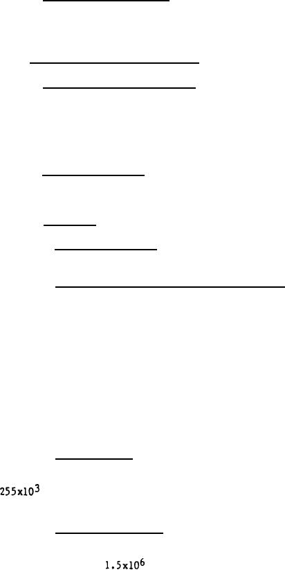
3.4.3.3 Resistor R4. Resistor R4 shall have a sheet
resistivity such that a single straight laser cut greater than .100
inch is required in order for R4 to be trimmed to a resistance equal
to
ohms. In addition, the resistor element width after
trimming shall nowhere be less than .010 inch.
3.4.3.4 Resistor R6, R10. Resistors R6 and R10 shall have a
sheet resistivity such that a single straight laser cut greater than
.060 inch is required in order for them to be trimmed to a
resistance equal to
ohms. In addition, the resistor
element width after trimming shall nowhere be less than .010 inch.
3
|
|
Privacy Statement - Press Release - Copyright Information. - Contact Us |