 |
|||
|
|
|||
| ||||||||||
|
|  MIL-R-83407B
4.5.8 Contact resistance (see 3.11). Relays shall be tested in accordance with method 307 of MIL-STD-202. The
following details and exceptions apply:
a. Method of connection: Between the measuring apparatus and the relay terminals (for relays with wire lead
terminals, this measurement shall be made .5 .094 inch from the emergence of the lead from the relay).
Voltage-sensing leads shall be connected in such a way as to exclude the resistance of the current-carrying
leads.
b. Test load: 100 mA at 6 V dc.
c. Points of measurement: All mated contacts in their closed position; the coil shall be energized with rated
voltage if necessary to effect contact closure.
d. Number of activations prior to measurement: None.
e. Number of test actuations: Three (the contact load shall not be applied during contact transfer). For quality
conformance inspection, one test actuation shall be made.
f. Number of measurements per actuation: One in each closed contact position.
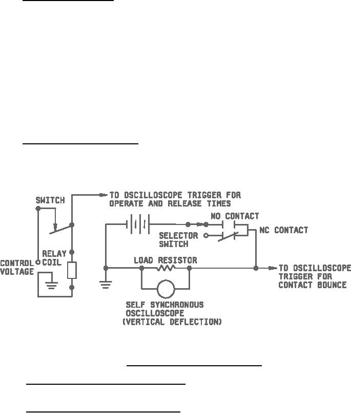
4.5.9 Operate and release times (see 3.12). The operate and release times shall be measured using an
oscilloscope. Rated voltage shall be applied to the coil. The circuit shown in figure 1, or equivalent, shall be used.
For qualification inspection, timing measurements shall be made on all contact sets. For quality conformance
inspection, all open contacts may be wired in series, and all closed contacts may be wired in parallel.
NOTE: The horizontal scan rate of the oscilloscope shall show the required pertinent data.
FIGURE 1. Typical circuit for operate and release times.
4.5.10 Coil inductance (when specified) (see 3.1 and 3.13). Coil inductance shall be measured at 1,000 Hz, using
a conventional impedance bridge.
4.5.11 Contact noise (when specified) (see 3.1 and 3.14). Contact noise shall be measured using the test circuit
shown in figure 2. The relays shall be operated with rated voltage at a rate of 60 to 100 Hz with "on" and "off" time
approximately equal. The input filter bandwidth of the oscilloscope shall be set at 600 Hz to 100 kHz. An
oscilloscope, such as a Tektronix Incorporated type 561A, with type 2A61 plug-in or equivalent, shall be used, with
its time scale adjusted to 2 ms per centimeter and its gain control adjusted for adequate deflection. The peak to
peak voltage shall be measured and the oscilloscope trace shall be recorded using an oscilloscope record camera.
10
|
|
Privacy Statement - Press Release - Copyright Information. - Contact Us |
