 |
|||
|
Page Title:
Figure 1.Outline dimensions and configuration of relay |
|
||
| ||||||||||
|
|  MIL-R-83726/13G
NOTES:
1. Dimensions are in inches.
2. Metric equivalents are given for general information only.
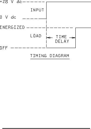
3. Load is connected between B+ and terminal designated LOAD. Delay begins upon application of
power to terminals (B+) and (B-). Upon completion of delay period, circuit from load terminal to
ground is completed. (B+) and (B-) are shown for reference only; they do not appear on the
relay.
4. Unless otherwise specified, tolerance is .010 (0.25 mm).
5. This is an active pin. Do not connect this pin to any portion of the circuit or ground.
FIGURE 1. Outline dimensions and configuration of relay - Continued.
REQUIREMENTS:
Operational data:
Timing action: Delay-on-operate.
Timing delay: Fixed time, 50 milliseconds to 600 seconds. See table I.
Timing accuracy: 10 percent of the nominal timing under all conditions of input voltage and
environmental extremes.
Recycle characteristics:
Before time out: A power interruption occurring after the start but before completion of the
timing cycle shall be for a duration of 0.5 percent of the nominal time delay or 10 ms, whichever
is greater, to ensure a loss in timing no greater than 10 percent.
After time out: A power interruption of 0.5 percent of nominal time delay or 10 ms, whichever is
greater, will initiate a new timing cycle with a loss in timing no greater than 5 percent.
2
|
|
Privacy Statement - Press Release - Copyright Information. - Contact Us |
