 |
|||
|
Page Title:
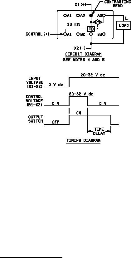
Figure 1. Dimensions and configuration |
|
||
| ||||||||||
|
|  MIL-R-83726/25H
Inches
mm
.001
0.03
.002
0.05
.003
0.08
.005
0.13
.010
0.25
.015
0.38
.040
1.02
.050
1.27
.055
1.40
.075
1.90
.080
2.03
.110
2.79
.130
3.30
.150
3.81
.158
4.01
.170
4.32
.200
5.08
.410
10.41
.640
16.26
.810
20.57
NOTES:
1. Dimensions are in inches.
2. Unless otherwise specified, tolerance is .010 (0.25 mm).
3. Metric equivalents are given for general information only.
4. Terminals A1, A2, B1, and B2 are connected internally. Do not use for external tie points or for
terminals.
5. There shall be affixed to the relay a legible circuit diagram that identifies each terminal location
specified.
6. Relays are intended for use with socket mount MIL-PRF-12883/52 and bracket mount MIL-PRF-
12883/53.
7. Terminal plating: Shall provide the operational, environmental, and interface characteristics to
provide a reliable interconnect to gold plated contacts. Terminals except for the polarizing pin,
shall be gold plated. One system for gold plating that may be used is ASTM B488, type 3, class
1.25 with a nickel underplate of 50 to 150 microninches thick. The gold plating system shall
enable the product to meet the performance requirements of this specification and shall be
approved by the qualifying activity.
FIGURE 1. Dimensions and configuration - Continued.
2
|
|
Privacy Statement - Press Release - Copyright Information. - Contact Us |
